1 resolver input connections, 2 analog input connections – Rockwell Automation SA3100 Power Module Interface (PMI) Regulator User Manual
Page 57
Installation Guidelines
5-7
5.3.1.1 Resolver Input Connections
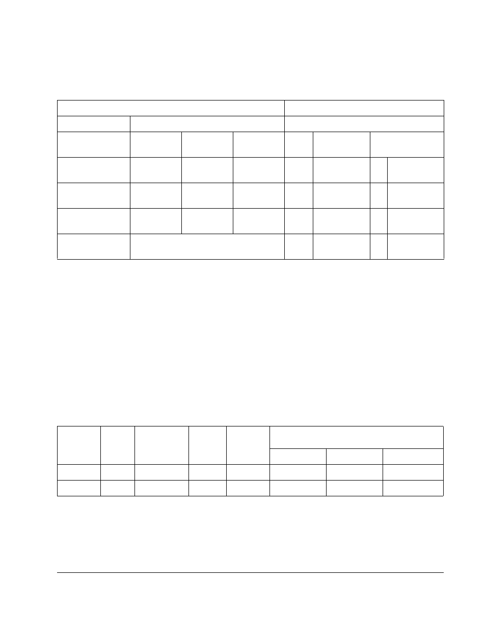
Standard resolver input connections are shown in table 5.1.
Typical voltage levels associated with the resolver are as follows:
•
Reference: This is a 2381 Hz sine wave with a typical amplitude of approximately
26V RMS. When measuring any of the resolver signals, make sure that the meter
used can respond to 2381 Hz accurately or use an oscilloscope.
•
Sine or cosine feedback: This is a 2381 Hz signal with an amplitude that varies
with the rotation of the shaft. Maximum amplitude (as the shaft turns) should be
approximately 11.8V at the resolver module. Voltages may be different depending
on the installation. The system adjusts the signal levels to develop 11.8V maximum
at the module input.
Table 5.2 lists the cables that may be used for resolver connection.
5.3.1.2 Analog Input Connections
Use 0.823 - 0.326 mm
2
(18-22 AWG) twisted pair shielded cable to connect the
analog device to the terminal block. Connect the shield to the SHIELD terminal.
Typical field connections are shown in figures 5.6 to 5.11. Note that Vc may appear as
induced noise voltage on otherwise floating inputs.
Table 5.1 – Standard Resolver Connections
Resolver
Resolver & Drive I/O Board
Connector Pin
Resolver
Winding
613469-1,-2
800123,
800123-1
800123-2
TB
Faceplate
Conn Pin
Resolver Module
Ref. Input
R1+
R2–
A
B
1
2
A
B
1
2
A
B
+
–
Ref. Output
Sine Output
S1+
S3–
C
D
3
4
D
F
3
4
D
C
+
–
Sine Input
Cosine
Output
S2+
S4–
E
F
5
6
G
E
5
6
F
E
–
+
Cosine Input
1
7
8
H
J
+
–
Ext. Strobe
1. Connections listed give a positive speed signal for counter-clockwise motor rotation (when facing the end opposite the output shaft). To
reverse the polarity of this signal, interchange the cosine input leads (terminals 5 and 6).
Table 5.2 – Resolver Cables
Part No.
417900-
No. of
Twisted
Pairs
Length
of Twist
Twists
Per Inch
Size mm
2
(AWG)
Recommended Maximum
Distance Per Resolver Type
X1
X2
X5
-207CG
3
12.7(8.5 mm)
2(3)
0.823 (18)
255 m (850 ft)
240 m (800 ft)
150 m (500 ft)
-76EAD
1
12.7(8.5 mm)
2(3)
1.31 (16)
320 m (1050 ft)
310 m (1025 ft)
190 m (625 ft)