4 synchronous transfer port – Rockwell Automation SA3100 Power Module Interface (PMI) Regulator User Manual
Page 33
PMI Regulator Motherboard
2-17
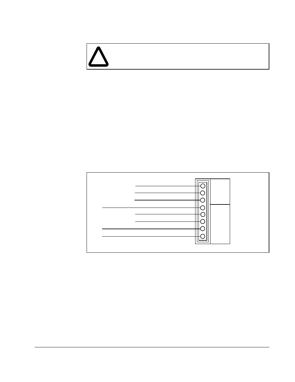
2.2.4 Synchronous Transfer Port
The synchronous transfer port is reserved for future use of the synchronous transfer
function. However, connections may be made to three pins in order to measure real-
time current feedback. Figure 2.7 shows the pinout for the Synchronous Transfer
connector.
Pins 7 and 8 are resistor-isolated copies of the analog motor current feedback signals.
These signals may be temporarily connected to an oscilloscope or high-speed strip
chart recorder to aid in start-up, tuning, or troubleshooting. Pin 4 is connected to
circuit common and should be used as the ground reference. These signals are not
isolated and pin 4 connects directly to the internal circuit common. Keep lead lengths
short and use isolated instruments to avoid introducing noise into the Regulator.
Important: These signals should not be permanently connected and should not leave
the cabinet.
Do not connect anything to pins 1, 2, 3, 5, and 6. These pins are reserved for future
functionality. Connecting to them may cause improper system operation.
!
ATTENTION: Do not connect anything to pins 1, 2, 3, 5, and 6 of the
Synchronous Transfer Connector. Connecting to these pins could result
in improper system operation. Failure to observe this precaution could
result in damage to equipment and bodily injury.
Figure 2.7 – Synchronous Transfer Port Connector Pinout
COM
BC
AB
I
N
COM
VW
UV
IU
IW
O
U
T
SEE ATTENTION
SEE ATTENTION
SEE ATTENTION
SEE ATTENTION
SEE ATTENTION
GROUND
PHASE U CURRENT MONITOR
PHASE W CURRENT MONITOR
1
2
3
4
5
6
7
8