Rockwell Automation SA3100 Power Module Interface (PMI) Regulator User Manual
Page 43
Resolver & Drive I/O Board
3-9
After any of these events, the PMI processor will wait until it detects that current
feedback is less than 2% of rated motor current multiplied by the motor overload ratio.
If this current level has not been reached within 300 msec, the PMI processor will turn
off the MCR output regardless.
If the RPI signal is removed, the MCR output will be turned off and gate power will be
removed under hardware control within approximately 0.5 second to provide an
additional level of protection.
The user has the option of having an M-contactor on the output of the drive (i.e., an
output contactor). This option is available during UDC parameter configuration. The
M-contactor is controlled by the MCR output, which is under the control of the PMI
processor. If the choice is made to connect the MCR to the output contactor, the
contacts must be wired to the AUX IN1/MFDBK input. The system will then wait for
MFDBK to turn on before executing the control algorithm. If this configuration choice is
not made, the AUX IN1 input can be used for any user-designated purpose.
The status of the drive I/O is indicated in UDC register 201/1201 and by eight of the
PMI Regulator status LEDs. In the event of a power loss or a system reset command
initiated by the PMI processor, all outputs are turned off.
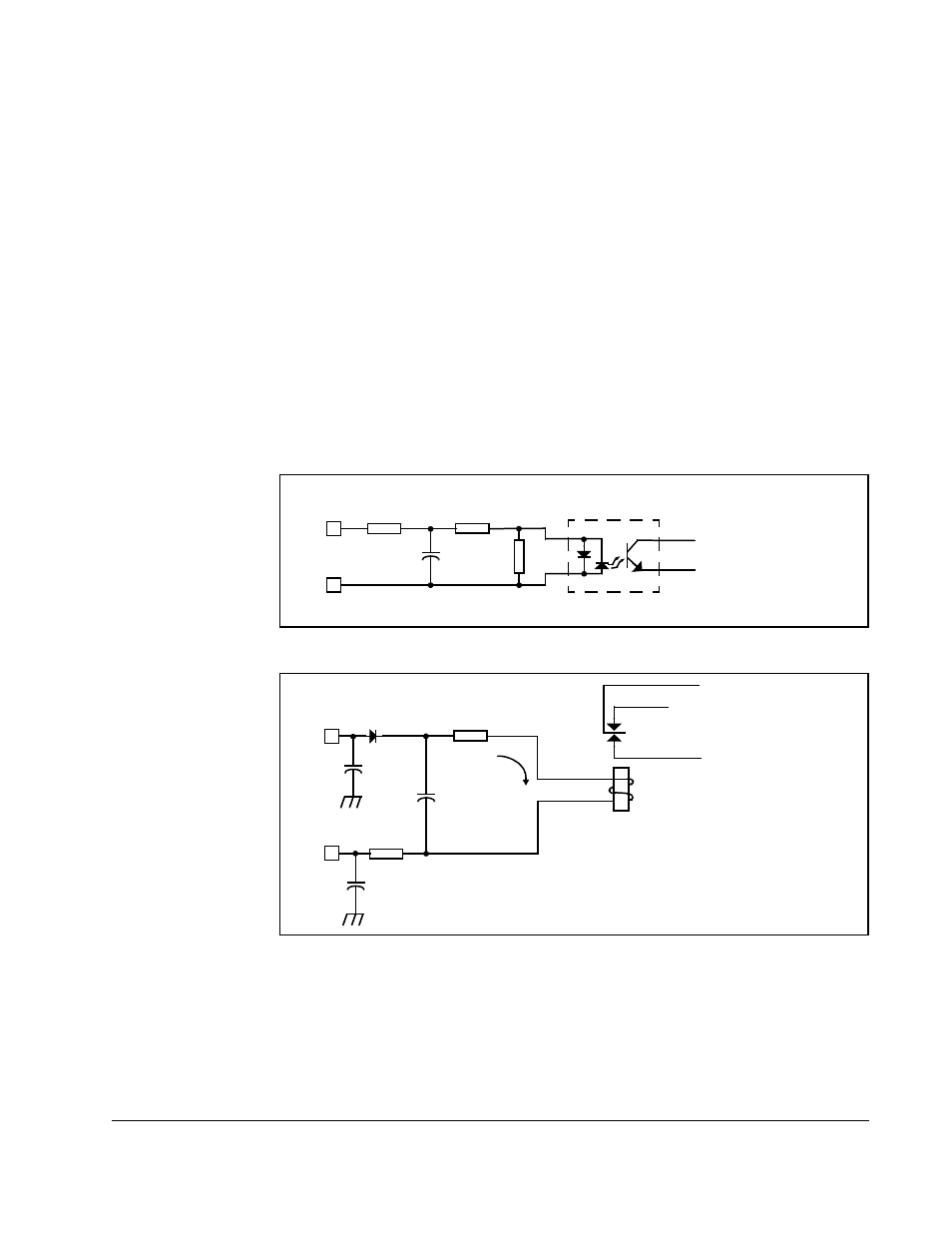
Figure 3.8 – Auxiliary Input Circuit
Figure 3.9 – Run Permissive Input (RPI) Circuit
330
15K
182
AUX INPUTS
DIGITAL
OUT TO
MICROPROCESSOR
.1uF
13K
RPI INPUT
.0033uF
2.2uF
12mA Pk
+
–
DIGITAL OUT
TO MICROPROCESSOR
AND MCR RELAY
.0033uF
100