1 flex i/o interface mechanical description, 2 flex i/o interface electrical description – Rockwell Automation SA3100 Power Module Interface (PMI) Regulator User Manual
Page 49
Flex I/O Interface
4-3
4.1
Flex I/O Interface Mechanical Description
The Flex I/O interface consists of:
•
A serial bus master (SERBUS) chip that controls the operation of the Flex I/O
module via software commands from a main processor. This IC performs all the
controlling functions occurring on the Flex I/O module. It also contains a dual-port
memory, which provides both the PMI processor and the Flex I/O modules access
to the same memory locations.
•
EMI, ESD filtering and suppression components for each signal entering or exiting
the Flex I/O module through the I/O cable connector.
•
A 20-pin sub-miniature D-shell connector for the Flex I/O cable that connects to the
Flex I/O modules.
•
A Generic Array Logic (GAL) chip for miscellaneous logic functions.
4.2
Flex I/O Interface Electrical Description
The transfer of data between the Flex l/O modules and the PMI Regulator dual-port
memory is coordinated by the serial bus master (SERBUS) IC. The SERBUS
addresses an I/O module, transfers data first from the I/O module to the dual-port
memory, and then from the dual-port memory to the I/O module. The SERBUS then
moves on to the next available I/O module. This process is repeated until all I/O
modules have been serviced, at which point the entire cycle is repeated, beginning
again with the first module. If one or more of the I/O modules is missing, the SERBUS
will simply move on to the next available I/O module.
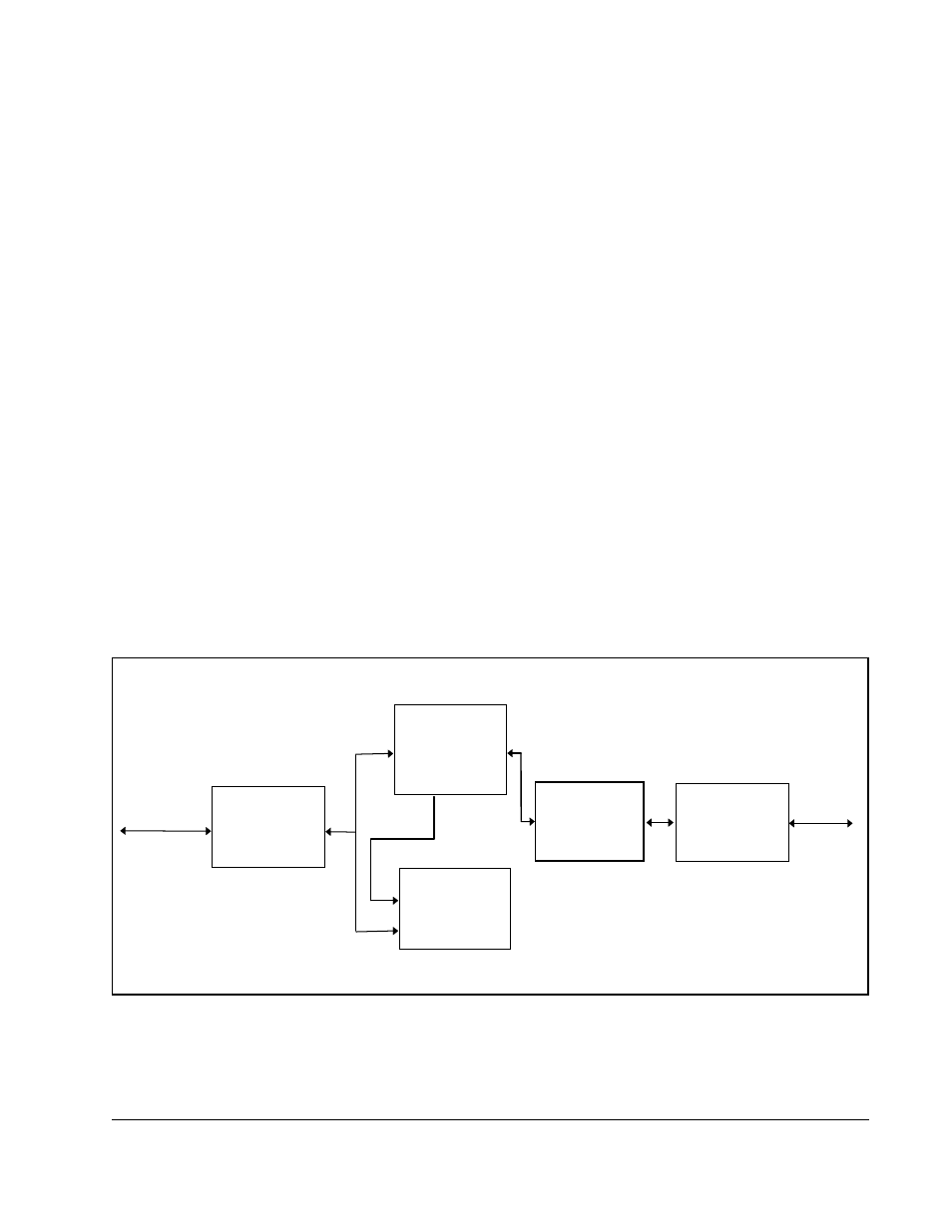
A block diagram of the Flex I/O interface is shown in figure 4.1.
Figure 4.1 – Flex I/O Interface Block Diagram
ASIC
PROCESSOR
CONNECTOR
FLEX BUS
CONNECTOR
MISC.
LOGIC
ADDR,DATA,
CNTRL
DISCRETE
FILTER &
PULLUP
COMPONENTS
FLEX I/O INTERFACE
+5VDC
@ 1A