Rockwell Automation SA3100 Power Module Interface (PMI) Regulator User Manual
Page 38
3-4
PMI Regulator
The Resolver & Drive I/O board supports two methods of sampling the digital position
of the resolver. In the first method, the position is sampled once per UDC task scan at
the rate defined in the SCAN_LOOP control block in the UDC task. This block tells
the UDC task how often to run based on the CCLK signal on the AutoMax rack
backplane. The PMI processor sends the position data to the UDC module
immediately before it is needed by the UDC module for the next UDC task scan.
Position data measured using this method is stored in the UDC module’s dual port
register 215/1215 in the format shown in figure 3.3 or 3.4.
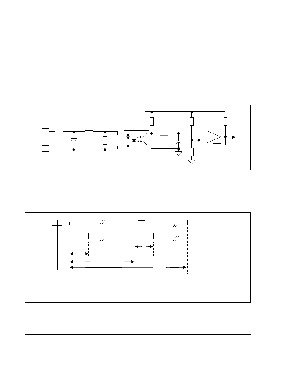
The second method allows position sampling between scans or when an external
event occurs by using an external strobe. The Resolver & Drive I/O board provides an
isolated 24 volt DC input with a relatively high degree of filtering (approximately 800
Hz). The external strobe input circuit is shown in figure 3.5.
Figure 3.6 shows the relationship between the time the external strobe is detected
and the point at which the resolver position is sampled. Response time is subject to
temperature, component tolerance, and input voltage level. Note that the input signal
pulse width should be greater than 300 µsec and the frequency should be less than
1000 pulses per second.
Figure 3.5 – External Strobe Input Circuit
+
-
EXTERNAL
STROBE
INPUT
300
300
.33uF
2.55K
1.24K
5K
Vcc
681K
10K
TO
MICRO-
PROCESSOR
14K
.01uF
681K
475K
Figure 3.6 – External Strobe Input Circuit Timing Diagram
EXT. STROBE
INPUT
RESOLVER
POSITION
LATCH
COMMAND
24 V NOM
T
pw
T
d
T
d
T
per
T
d
- 250
m
SEC TYP.
T
pw
- 300
m
SEC MIN.
T
per
- 1000
m
SEC MIN.