Chapter 3 resolver & drive i/o board, Hapter, Resolver & drive i/o board – Rockwell Automation SA3100 Power Module Interface (PMI) Regulator User Manual
Page 35
Resolver & Drive I/O Board
3-1
C
HAPTER
3
Resolver & Drive I/O Board
The Resolver & Drive I/O board (B/M O-60067) converts analog sine and cosine
resolver feedback signals into digital format for use within the application program. An
external strobe input is also provided to permit a user-generated signal to latch the
resolver position data. The board self-tunes to compensate for varying lengths and
types of resolver wiring. Distributed Power Systems are designed to be used with the
standard resolvers described in Appendix B.
The Resolver & Drive I/O board provides an analog input connection that can be used
for an analog tachometer or other user input device. It also provides digital I/O
connections which can be used for standard drive-related signals, such as motor
thermal overload.
For applications using the V/Hz regulator, the board may be supplied with Drive I/O
funtionality only (B/M O-60068).
The following sections provide mechanical and electrical descriptions of the Resolver
& Drive I/O board. Figures 3.12 and 3.13 at the end of this chapter show functional
block diagrams of the two versions of the board.
3.1
Resolver & Drive I/O Board Mechanical Description
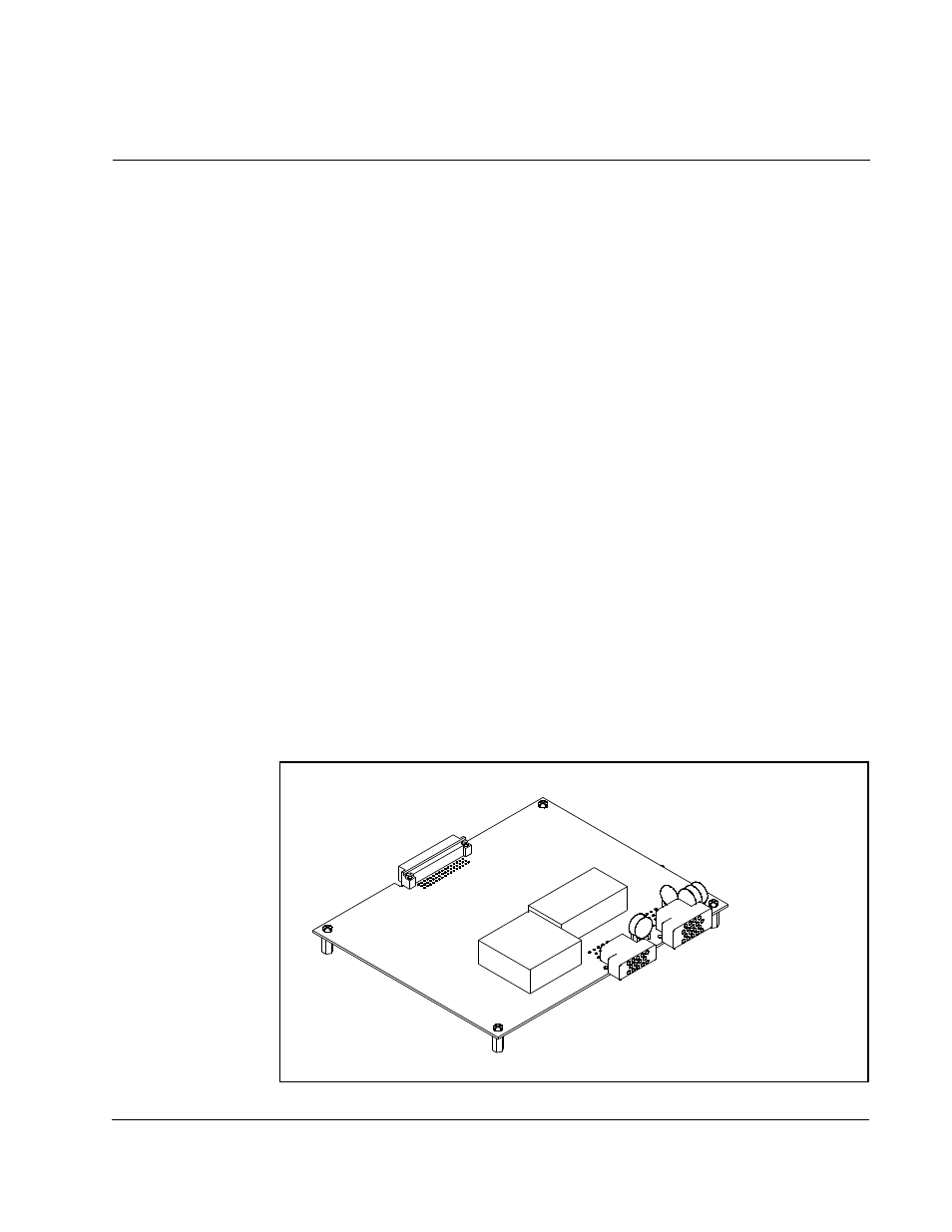
The Resolver & Drive I/O board is a printed circuit board assembly that mounts on
standoffs above the PMI Regulator motherboard. The board consists of the resolver
and drive I/O circuitry, a 48-pin DIN style backplane connector that interfaces to the
PMI Regulator motherboard, and two connectors for the resolver and drive I/O. The
board is fastened to the standoffs at its four corners. Board dimensions are listed in
Appendix B.
Figure 3.1 – Resolver & Drive I/O Board
DRIVE I/O
CONNECTOR
RESOLVER FEEDBACK
CONNECTOR
BACKPLANE
CONNECTOR