Chapter 4 flex i/o interface, Hapter, Flex i/o interface – Rockwell Automation SA3100 Power Module Interface (PMI) Regulator User Manual
Page 47
Flex I/O Interface
4-1
C
HAPTER
4
Flex I/O Interface
The Flex I/O interface provides the hardware connection between the PMI processor
and the Flex I/O modules that are used to read and write analog and digital data to or
from external devices. Flex I/O plugs into a terminal base and is mounted on DIN rails.
The terminal bases plug into each other to connect and daisy-chain power and
communication signals.
Module numbering is used to determine where in the UDC memory map the I/O data
is placed. Modules 0 and 1 must be digital I/O. Module 2 can be digital or analog I/O.
Module numbering is determined by the physical location on the DIN rail. Cable
connection from the PMI Regulator to the Flex rail is at the right side of the rail.
Module numbering is done right to left on the DIN rail.
The farthest right (closet to the cable) digital I/O module is Module 0, the next digital
I/O module to the left is Module 1. Only one analog I/O module can be used, and it is
always Module 2. Module 2 is always the farthest module from cable. If an analog
module is used it MUST be the farthest module from the cable connection. When the
operating system reads an analog module, it will not read any more modules.
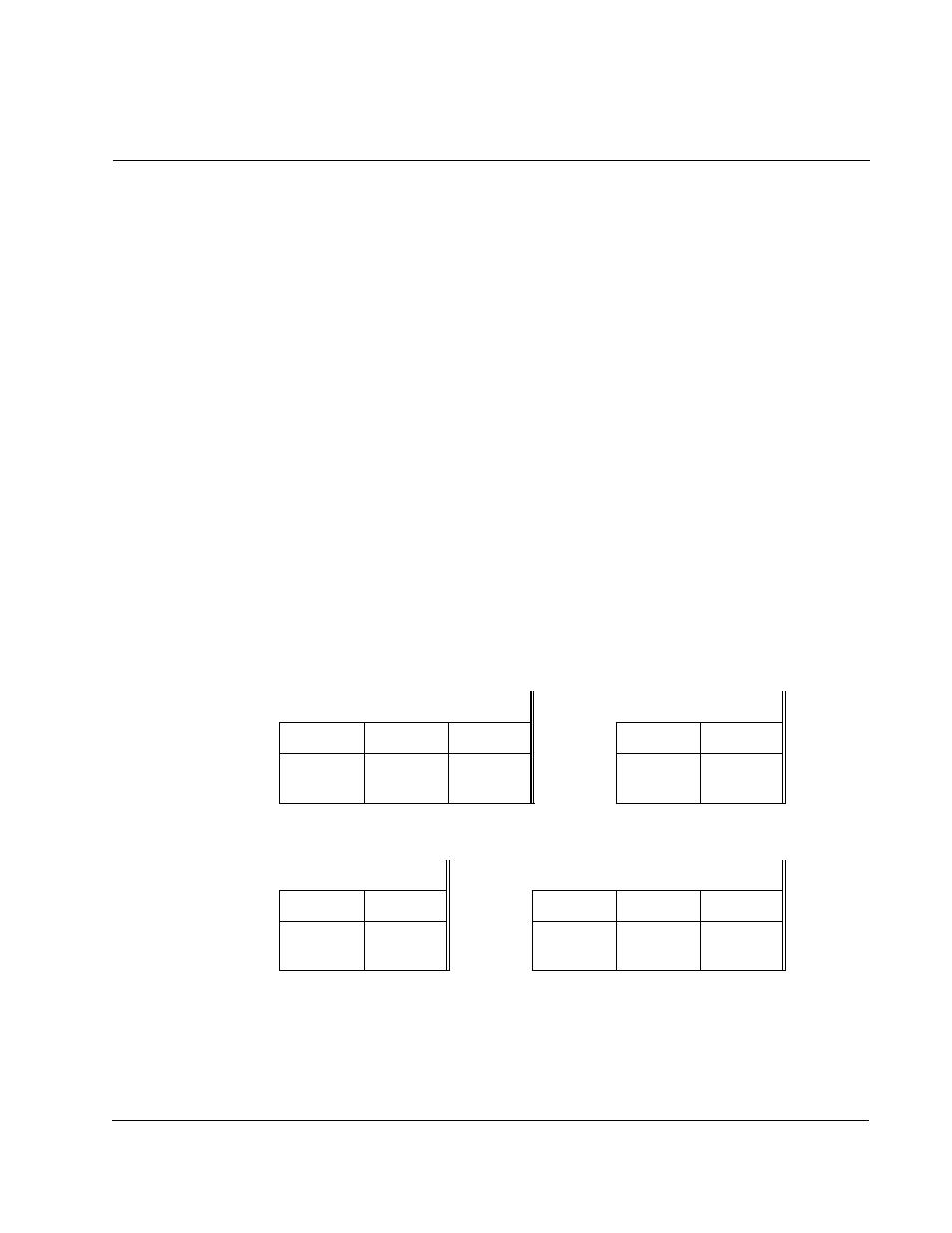
Shown below are four possible legal physical location combinations and their module
numbering:
LEGAL COMBINATIONS OF FLEX I/O:
Interface Cable
Interface Cable
MOD 2
MOD 1
MOD 0
MOD 1
MOD 0
DIGITAL
I/O
DIGITAL
I/O
DIGITAL
I/O
DIGITAL
I/O
DIGITAL
I/O
Interface Cable
Interface Cable
MOD 2
MOD 0
MOD 2
MOD 1
MOD 0
ANALOG
I/O
DIGITAL
I/O
ANALOG
I/O
DIGITAL
I/O
DIGITAL
I/O