Installing i/o modules – Rockwell Automation 2755 Enhanced Decoder Series B User Manual
Page 58
4–19
Installing the Decoder
Publication 2755-833
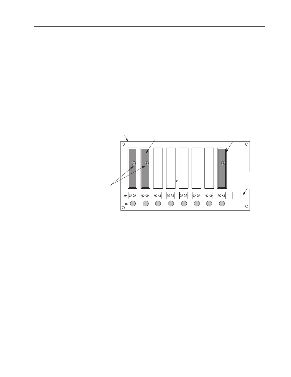
This section shows how to install input and output modules on the
optional I/O Module Board. The board has eight positions
(MOD1-MOD8) for I/O modules. All eight positions accept output
modules. The MOD8 position alternately accepts an input module
for the match code AutoLoad function.
The Accessories section in Chapter 2 provides a complete list of
modules supported by the I/O board.
Figure 4.11 shows two output modules installed in the MOD1 and
MOD2 positions and one input module in the MOD8 position. A
screw holds each module into position on the I/O board.
Figure 4.11 I/O module board (with optional I/O modules
installed
I/O Modules
Module
Connectors (8)
Hold
Down
Screws
I/O Board
Fuses (F1 - F8)
MOD2
MOD3
MOD4
MOD6
MOD7 MOD8
–
1 +
MOD1
–
+
12 V
DC
–
2 +
–
3 +
–
4 +
MOD5
–
5 +
–
6 +
–
7 +
–
8 +
F
1
F
2
F
3
F
4
F
5
F
6
F
7
F
8
12V DC Power
Source (100 mA
Max) for Autoload
Input Only
MOD8 accepts
input or output
module
To install a module on the I/O board:
1. Verify that power is disconnected from decoder and module
connectors.
2. Loosen the two screws which secure the cover of the decoder and
open.
3. Carefully align module pins over sockets in board. Plug module
into MOD position on I/O board.
4. Note: The module pins must puncture the silicon seal of the
I/O board sockets.
5. Tighten the hold-down screw to secure module in position.
To remove a module, verify that the power is off, loosen the
hold-down screw, and pull out module.
Installing I/O Modules