Connecting the aux terminal – Rockwell Automation 2755 Enhanced Decoder Series B User Manual
Page 54
4–15
Installing the Decoder
Publication 2755-833
6. Adjust the position of the scanner to maximize decoder
performance.
7. Fix the scanner in this optimized position.
Customize As Required
Your system is now ready to customize for best performance in your
particular application. The software screens used to do that have
been structured to “walk you through” the configuration process. We
recommend stepping through the screens in the order they appear,
using this manual as a reference.
If your application requires a host device or I/O modules, the next
two sections, “Connecting Host Device” and “Installing I/O
Modules” will help guide you through the hardware configuration
required to use them.
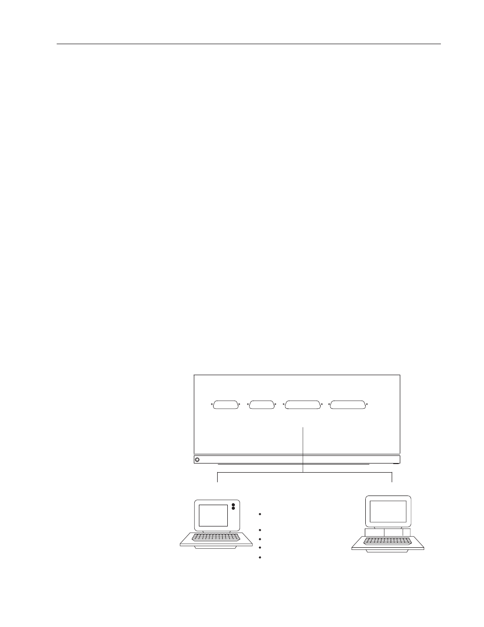
The AUX port supports a terminal for either configuring the decoder
or for manual data entry.
The AUX port on the NEMA Type 1 decoder is configured as shown
below, and communicates over an RS-232 serial communication line.
It has a 25-pin D shell (female) connector. Figure 4.7 shows
terminals you can connect to the AUX port of the NEMA Type 1
decoder.
Figure 4.7 Connecting terminal to AUX port of NEMA Type 1
decoder
Configuration
Manual
Data Entry
Supported Terminal Types
① Construct your own cable using
the pinouts in Appendix D.
Allen-Bradley Industrial Terminals
1771-T1, -T2, -T3
Allen-Bradley 1784-T45 Laptop Terminal
DEC VT100
Lear Siegler ADM 3E
Computer or terminal that emulates one
HOST
RS-232 /422 /485
SCANNER A SCANNER B
AUX
RS-232
①
of the above
Connecting the
AUX Terminal