Led indicators – Rockwell Automation 2755 Enhanced Decoder Series B User Manual
Page 20
2–3
Decoder Features
Publication 2755-833
Seventeen front panel indicators provide a visual indication of the
operating status of the dual-head decoders. There are fourteen front
panel indicators on single-head decoders. Table 2.A defines the color
and function of each LED.
Table 2.A
LED Indicators (NEMA Type 1 and Type 4 Decoders)
LED Label
Color
Lights when
Power
Green
The decoder is receiving power.
CPU Active
Green
The CPU is active and running. The LED turns off if a fault condition is detected.
Communications
Yellow
Data is transmitting to or from the AUX port or HOST port.
Laser On A
Red
Scanner A is activated to turn on its laser light source. ①
Trigger Active A
Yellow
The decoder is in triggered mode and scanning has been triggered for Scanner A or Scanner B.
Valid Read A
Green
A valid read occurs from Scanner A.
Laser On B
Red
Scanner B is activated to turn on its laser light source. ①. (Dual-head versions only)
Trigger Active B
Yellow
The decoder is in triggered mode and scanning has been triggered for Scanner A or B. (Dual-head versions only)
Valid Read B
Green
A valid read occurs from Scanner B. (Dual-head versions only)
Discrete I/O (1-8)
Red
Input/output module in position 1,2, 3, 4, 5, 6, 7, or 8 is active.
①
The LED will light even if the scanner is disconnected or the Laser On switch for the scanner is in
the OFF position.
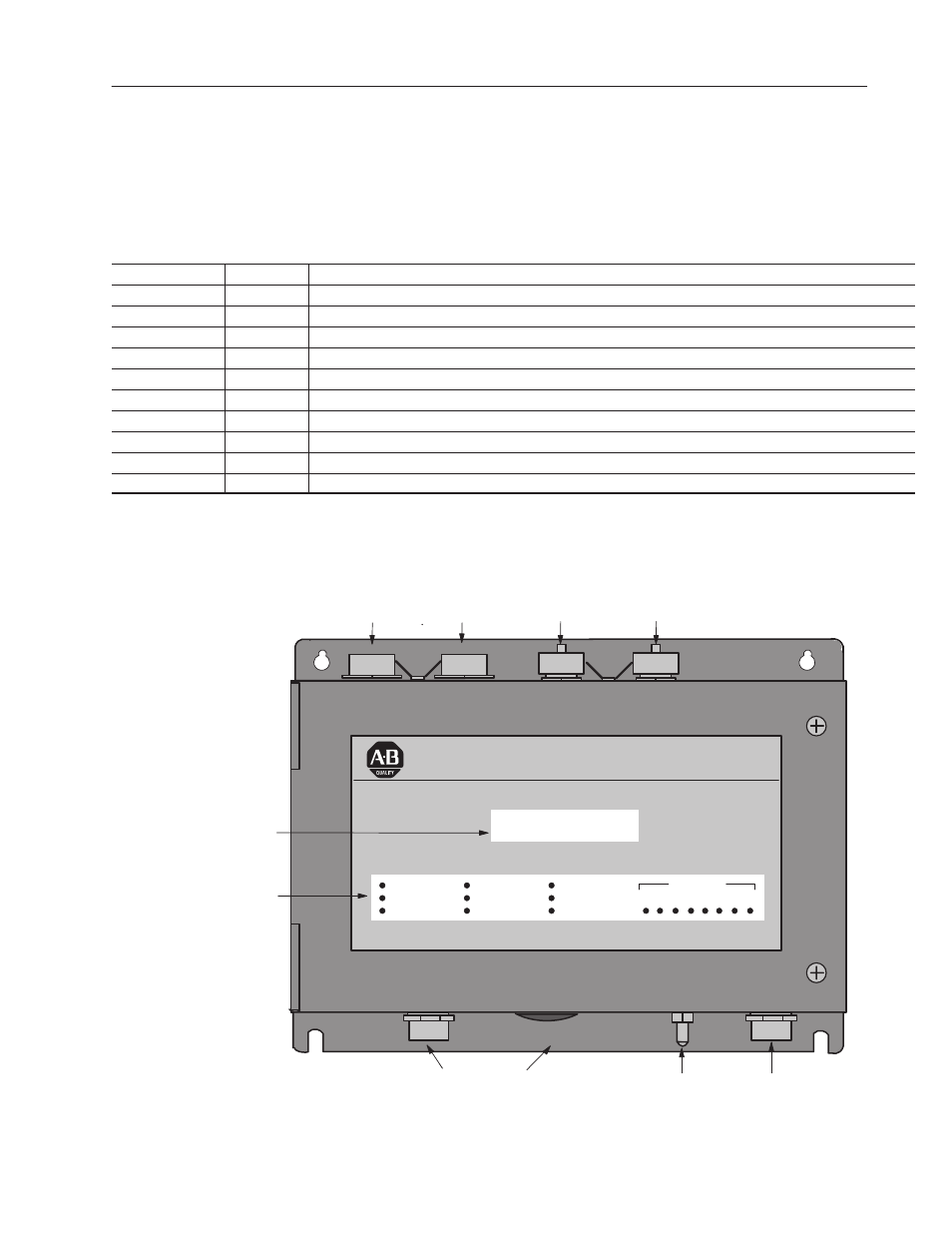
Figure 2.2
NEMA Type 4 Decoder (Catalog No. 2755-DD4A)
ALLEN-BRADLEY
BAR CODE DECODER
POWER
CPU ACTIVE
COMMUNICATION
LASER ON A
TRIGGER ACTIVE A
VALID READ A
LASER ON B
TRIGGER ACTIVE B
VALID READ B
DISCRETE I/O
1 2 3 4 5 6 7 8
Optional LCD Display
ON/OFF
Toggle Switch
NEMA Type 4
Power Connector
SCANNER A
Port
SCANNER B Port
(DD Versions Only)
AUX Port
RS-232
HOST Port
RS-232/422/485
LED Indicators
Holes for Conduit or Optional Output Module Connectors
(shown installed on left and plugged on right).
LED Indicators