Rockwell Automation 2755 Enhanced Decoder Series B User Manual
Page 57
4–18
Installing the Decoder
Publication 2755-833
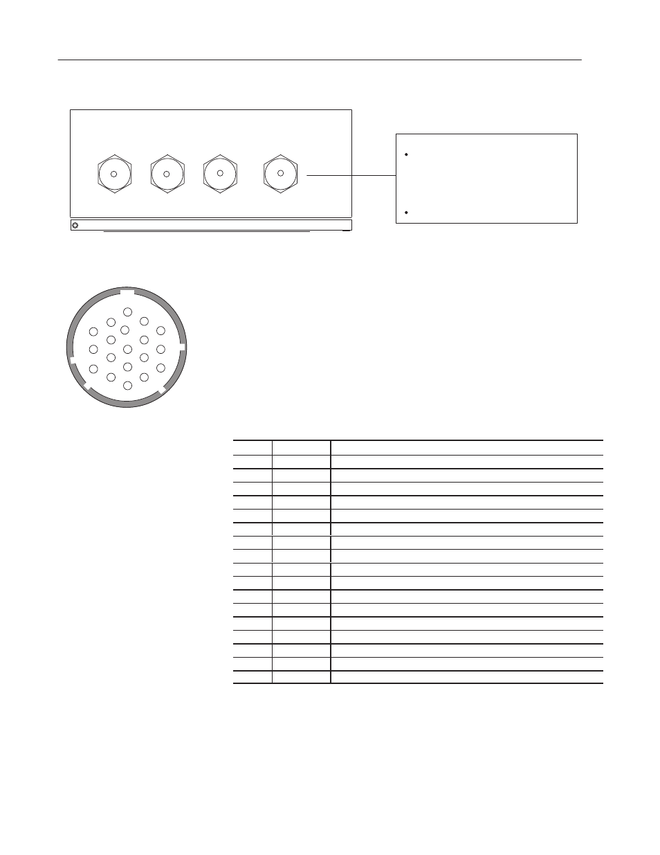
Figure 4.10 Connecting device to HOST port of NEMA Type
4 decoder
Use the Cat. No. 2755-CT1 communication
cable or construct your own cable using the Cat.
No. 2755-NC17 Connector Kit and the pinouts in
Appendix E. Use 2755-CY1 for multidrop
applications.
C
D
B
E
P
A
S
N
M
F
G
U
L
H
K
T
J
V
R
C
D
B
E
P
A
S
N
M
F
G
U
L
H
K
T
J
V
R
HOST Port (male) Connector
Allen-Bradley PLC Controller via:
Cat. No. 1771-DB BASIC Module
Any RS-232 or RS-422 ASCII Device
Cat. No. 1771-DA ASCII I/O Module
Cat. No. 2760-RB Flexible Interface Module
with Cat. No. 2760-SFC1/SFC2 Protocol Cartridge
Supported Host Devices
-
-
-
HOST
RS-232 /422 /485
SCANNER A SCANNER B
AUX
RS-232
①
①
Pin
Abbreviation
Function
A
GND
Chassis Ground
B
RD
RS-232 Receive Data (from host).
C
TD
RS-232 Transmit Data (from decoder to host).
D
SIG GND
RS-232 Signal Common
E
DTR
RS-232 Data Terminal Ready
F
RTS
RS-232 Request to Send
H
DSR
RS-232 Data Set Ready
J
CTS
RS-232 Clear to Send
L
SHLD
RS-485 Shield Ground
M
485 TERM
RS-485 Line Termination. Jumpers to N.
N
485 A/TERM
RS-485 Line Termination. Jumpers to M.
P
TxB+
RS-422 Transmit Data (from decoder to host).
R
TxA-
RS-422 Transmit Data (from decoder to host).
S
RxA ’-
RS-422 Receive Data (from host).
T
RxB ’+
RS-422 Receive Data (from host).
U
422 A/TERM
RS-422 Line Termination. Jumpers to V.
V
422 TERM
RS-422 Line Termination. Jumpers to U.
See Appendix E for specific details on connecting to a host device
using the different communication interfaces.