Allen-bradley 1784-t45 or t47 programming terminal – Rockwell Automation 2755 Enhanced Decoder Series B User Manual
Page 316
Setting Up Terminals
D–4
Publication 2755-833
Follow these steps if using an Allen-Bradley 1784-T45 or -T47
computer:
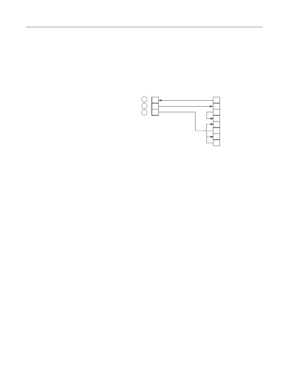
1. Construct a cable to connect the terminal to the decoder. Use a
Belden 8303, Alpha 45123, or equivalent type of cable. Use the
following connector pinouts:
2
3
7
2
3
4
Note: Connect shield to shell
of cable connectors at both ends.
Transmit Data
Receive Data
Signal Ground
5
6
7
8
20
.
DTR
CD
DSR
RTS
CTS
C
B
D
NEMA NEMA
Type 1
Type 4
25-pin Female
Decoder
Terminal
Male 19-pin NEMA Type 4 or Female
25-pin D Shell Connector
2. Power on the terminal. The switch is located on the left side of
the unit.
The terminal will beep once, and then test itself. When the test is
complete, a message appears. The last line should indicate that all
tests have passed.
3. Press [CTRL][ALT][CMD] key sequence to display the system
Main Menu (Press the [CMD] key while holding down both the
[ALT] and [CTRL] keys.
4. Set the T45 terminal emulation to the following settings (Refer to
the terminal documentation for additional information):
•
F1 DGC D200 Terminal
•
F2 Modem = External
•
F3 Flow Control = On
•
F4 Duplex = Full
•
F6 Print = Off
5. Set the COM1 parameters to:
•
F1 Baud Rate = 9600
•
F2 Parity = None
•
F3 Data Bits = 8
•
F4 Stop Bits = 1
•
F5 Type = Standard PC Compatible Com
Note: If using an internal modem, disable it using the MODE
command.
Allen-Bradley 1784-T45 or
T47 Programming
Terminal