Rockwell Automation 2755 Enhanced Decoder Series B User Manual
Page 56
4–17
Installing the Decoder
Publication 2755-833
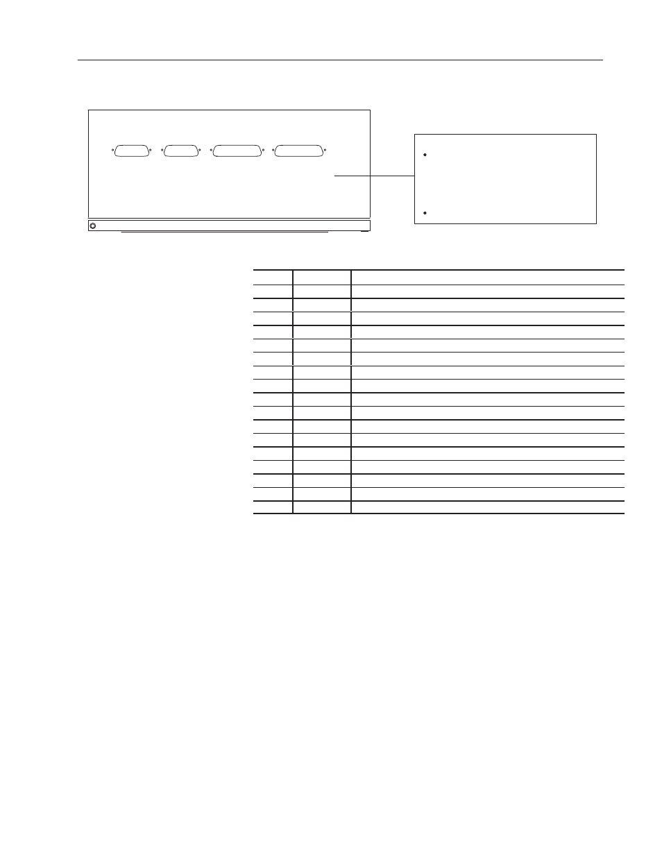
Figure 4.9 Connecting device to HOST port of NEMA Type 1
decoder
Allen-Bradley PLC Controller via:
Cat. No. 1771-DB BASIC Module
Any RS-232 or RS-422 ASCII Device
Cat. No. 1771-DA ASCII I/O Module
Cat. No. 2760-RB Flexible Interface Module
with Cat. No. 2760-SFC1/SFC2 Protocol Cartridge
Supported Host Devices
-
-
-
HOST
RS-232 /422 /485
SCANNER A SCANNER B
AUX
RS-232
①
① Construct your own cable using pinouts in Appendix E.
Pin
Abbreviation
Function
1
GND
Chassis Ground
2
TD
RS-232 Transmit Data (from decoder to host).
3
RD
RS-232 Receive Data (from host).
4
RTS
RS-232 Request to Send
5
CTS
RS-232 Clear to Send
6
DSR
RS-232 Data Set Ready
7
SIG GND
RS-232 Signal Common
9
SHLD
RS-485 Shield Ground
12
485 TERM
RS-485 Line Termination. Jumpers to 13.
13
485 A/TERM
RS-485 Line Termination. Jumpers to 12.
14
TxB+
RS-422(B) or RS-485(B) Transmit Data (from decoder to host).
15
TxA-
RS-422(A) or RS-485(A) Transmit Data (from decoder to host).
16
RxA ’-
RS-422 Receive Data (from host).
17
RxB ’+
RS-422 Receive Data (from host).
18
422 A/TERM
RS-422 Line Termination. Jumpers to 19.
19
422 TERM
RS-422 Line Termination. Jumpers to 18.
20
DTR
RS-232 Data Terminal Ready
The HOST port on the NEMA Type 4 decoder has a 19-pin (male)
connector and communicates over an RS-232, RS-422, or RS-485
communication line. Figure 4.10 shows host devices you can connect
to the HOST port of the NEMA Type 4 decoder.