Rockwell Automation 1798-IB4 FlexArmor User Manual User Manual
Page 26
Publication 1798-UM001B-EN-P - November 2002
2-12 How Communication Takes Place and I/O Image Table Mapping
Description of 1798-OE2 Image Table Mapping
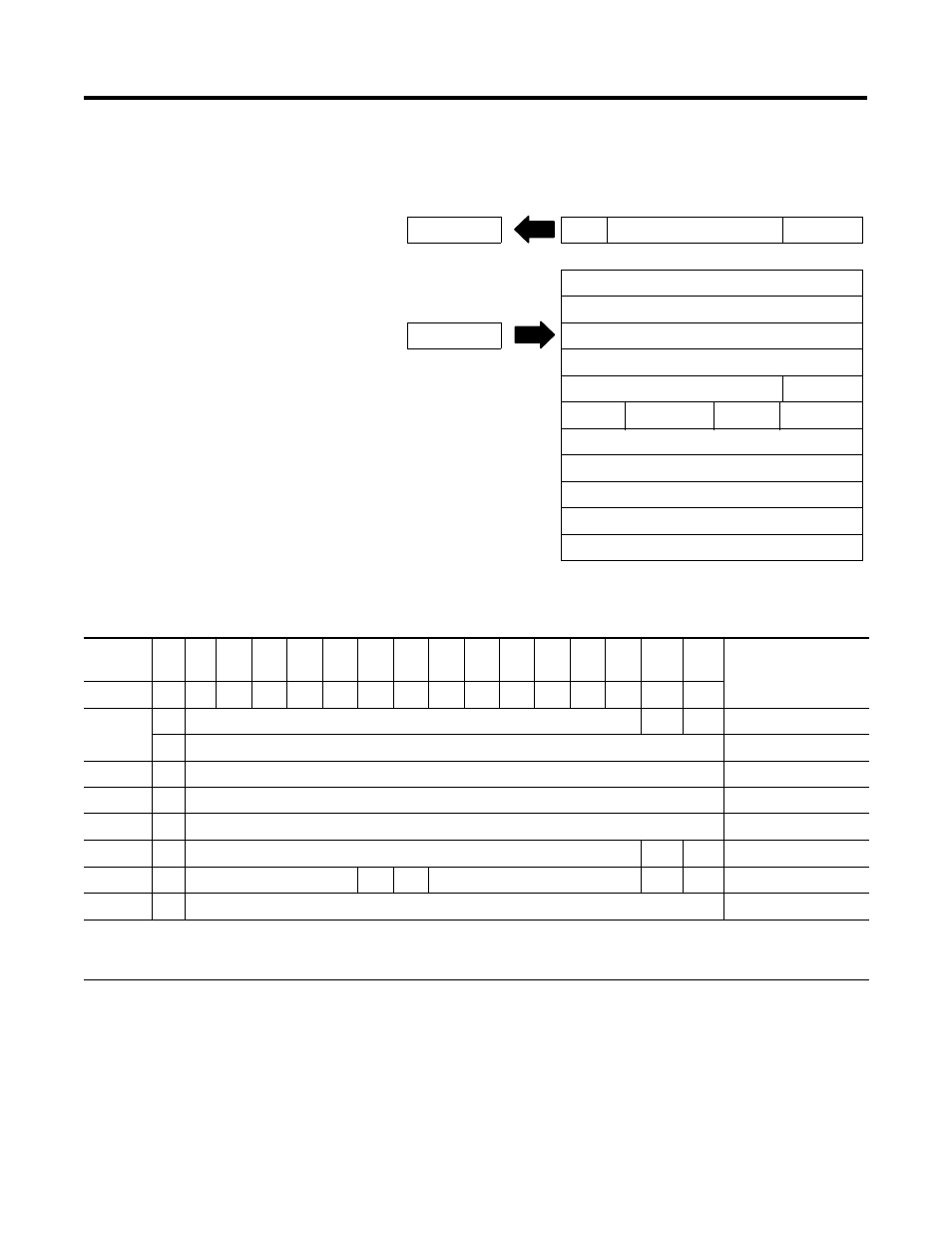
Memory Map of Analog Output Module Image Table - 1798-OE2
I/O Image
Input Size
0 to 1 Words
PU
Not Used
Diagnostics
Analog Output Data 0
Output Size
Analog Output Data 1
1 to 6 Words
Not Used
Not Used
Not Used
OE
Not Used Config. Select Not Used Full Range
Not Used
Not Used
Not Used
Not Used
Not Used
Decimal
Bit
15
14
13
12
11
10
09
08
07
06
05
04
03
02
01
00
Size
Octal Bit 17
16
15
14
13
12
11
10
07
06
05
04
03
02
01
00
PU
Not Used - Set to Zero
W1
W0
Read Word 1
S
Analog Value Channel 0
Write Word 1
S
Analog Value Channel 1
Write Word 2
S
Not Used
Write Word 3
S
Not Used
Write Word 4
S
Not Used - Set to 0
OE1 OE0 Write Word 5
S
Not Used - Set to 0
C1
C0
Not Used - Set to 0
F1
F0
Write Word 6
S
Not Used - Set to 0
Write Word 7 thru 14
Where PU = Power up bit; W = Diagnostic bits for current output broken or load resistance high (Not used on voltage
outputs.); OE = Output enable bits (bit 00 corresponds to output 0, bit 01 corresponds to output 1. ATTENTION: These bits
must be set to 1. C = Configure select bit; F = Full range bit; S = Sign bit (in 2’s complement)