Rockwell Automation 1798-IB4 FlexArmor User Manual User Manual
Page 24
Publication 1798-UM001B-EN-P - November 2002
2-10 How Communication Takes Place and I/O Image Table Mapping
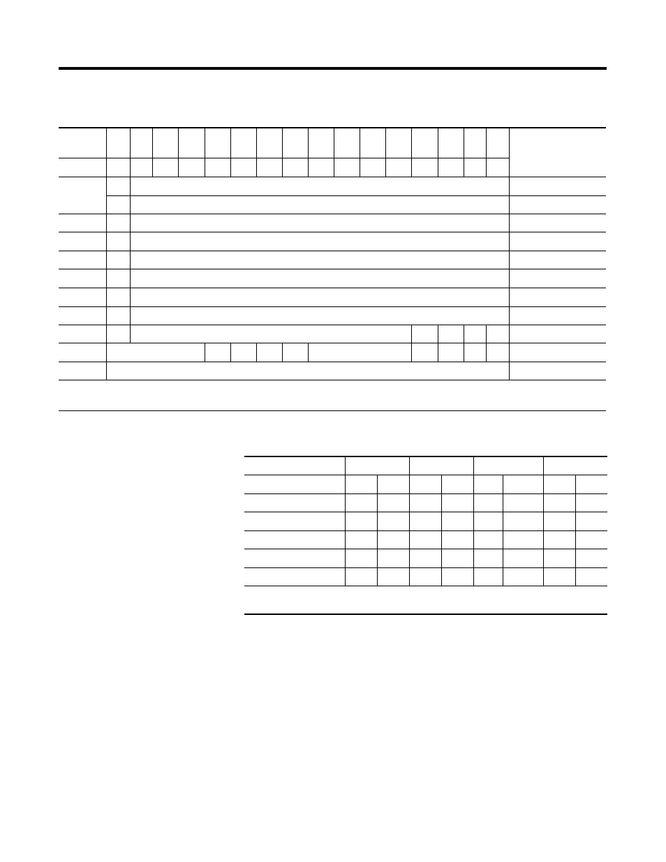
Memory Map of Analog Input Module Image Table - 1798-IE4
Range Selection Bits for the 1798-IE4
Decimal
Bit
15
14
13
12
11
10
09
08
07
06
05
04
03
02
01
00
Size
Octal Bit 17
16
15
14
13
12
11
10
07
06
05
04
03
02
01
00
S
Analog Value Channel 0
Read Word 1
S
Analog Value Channel 1
Read Word 2
S
Analog Value Channel 2
Read Word 3
S
Analog Value Channel 3
Read Word 4
S
Not Used
Read Word 5
S
Not Used
Read Word 6
S
Not Used
Read Word 7
S
Not Used
Read Word 8
PU
Not Used - Set to Zero
U3
U2
U1 U0 Read Word 9
Not Used - Set to 0
C3
C2
C1
C0
Not Used - Set to 0
F3
F2
F1
F0
Write Word 1
Not Used - Set to 0
Write Word 2 thru 6
Where PU = Power up bit; U = Underrange bits for 4-20mA inputs; C = Configure select bit; F = Full range bit;
S = Sign bit (in 2’s complement)
Channel No.
Channel 0
Channel 1
Channel 2
Channel 3
F0
C0
F1
C1
F2
C2
F3
C3
Decimal Bit
00
08
01
09
02
10
03
11
0-10V dc/0-20mA
1
0
1
0
1
0
1
0
4-20mA
0
1
0
1
0
1
0
1
10 to +10V dc
1
1
1
1
1
1
1
1
Off
1
0
0
0
0
0
0
0
0
C = Configure select bit; F = Full range bit
1. When configured to off, individual channels will return 0000H.