Rockwell Automation 1798-IB4 FlexArmor User Manual User Manual
Page 21
Publication 1798-UM001B-EN-P - November 2002
How Communication Takes Place and I/O Image Table Mapping 2-7
Input Delay Times for the 1798-IB4D Input Module
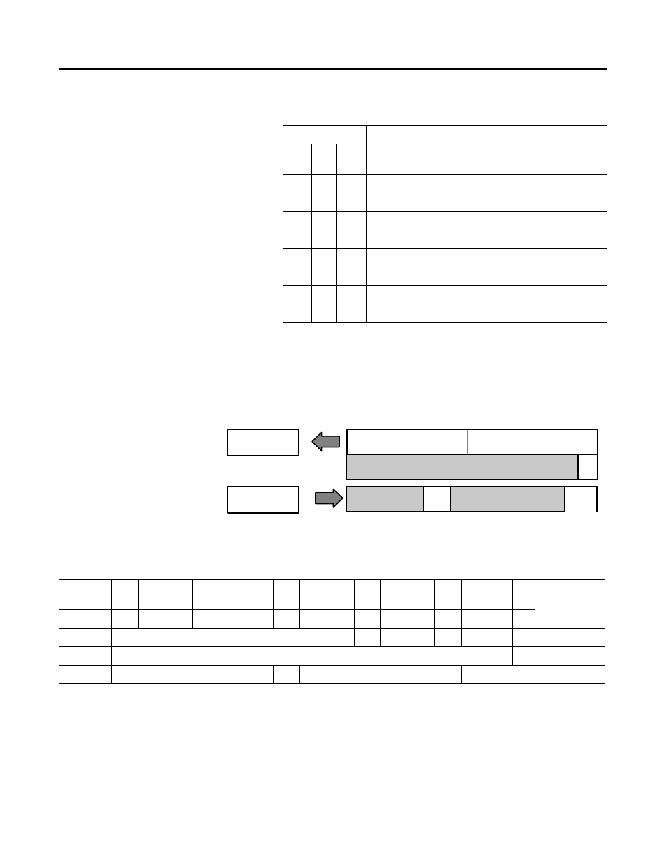
Description of 1798-IB8 Image Table Mapping
Memory Map of 8 Point Discrete Input Module Image Table - 1798-IB8
Bits
Description
Selected Delay Time
02
01
00
Delay Time for Inputs
00-03
0
0
0
Delay Time 0 (default)
256µs
0
0
1
Delay Time 1
512µs
0
1
0
Delay Time 2
1ms
0
1
1
Delay Time 3
2ms
1
0
0
Delay Time 4
4ms
1
0
1
Delay Time 5
8ms
1
1
0
Delay Time 6
16ms
1
1
1
Delay Time 7
32ms
I/O Image
Input Size
Module Image
1 or 2 Words
0 or 1 Word
Read
Write
Output Size
Inputs
Delay
Time
Not used
Reserved
Fault
Input
Fault
Enabled
Reserved
Reserved
42840
Decimal
Bit
15
14
13
12
11
10
09
08
07
06
05
04
03
02
01
00
Size
Octal Bit
17
16
15
14
13
12
11
10
07
06
05
04
03
02
01
00
Not used
D7
D6
D5
D4
D3
D2
D1
D0 Read Word 1
Not used
FO Read Word 2
Reserved
FE
Reserved
DT 00-07
Write Word 1
Where D = Input Data (D0 corresponds to input 0, D1 corresponds to input 1, etc.), DT = Input Delay Time (DT 00-07
corresponds to inputs 0 through 7) FO = Fault Bit - Indicates status of module sensor power (0=Normal, 1=Sensor Power
Shorted), FE = Fault Enabled Bit, must be set to return fault bit (FO) from module. The “Fault Enabled” bit will be set
automatically if the input filter times are configured through RSNetWorx for DeviceNet.