Chapter objectives, Communication over the flexarmor backplane, Chapter – Rockwell Automation 1798-IB4 FlexArmor User Manual User Manual
Page 15
1
Publication 1798-UM001B-EN-P - November 2002
Chapter
2
How Communication Takes Place and I/O
Image Table Mapping
Chapter Objectives
In this chapter, you will learn about:
•
communication over the FlexArmor backplane (between the
DeviceNet adapter and the I/O modules)
•
how data is mapped into the I/O image table
Communication Over the
FlexArmor Backplane
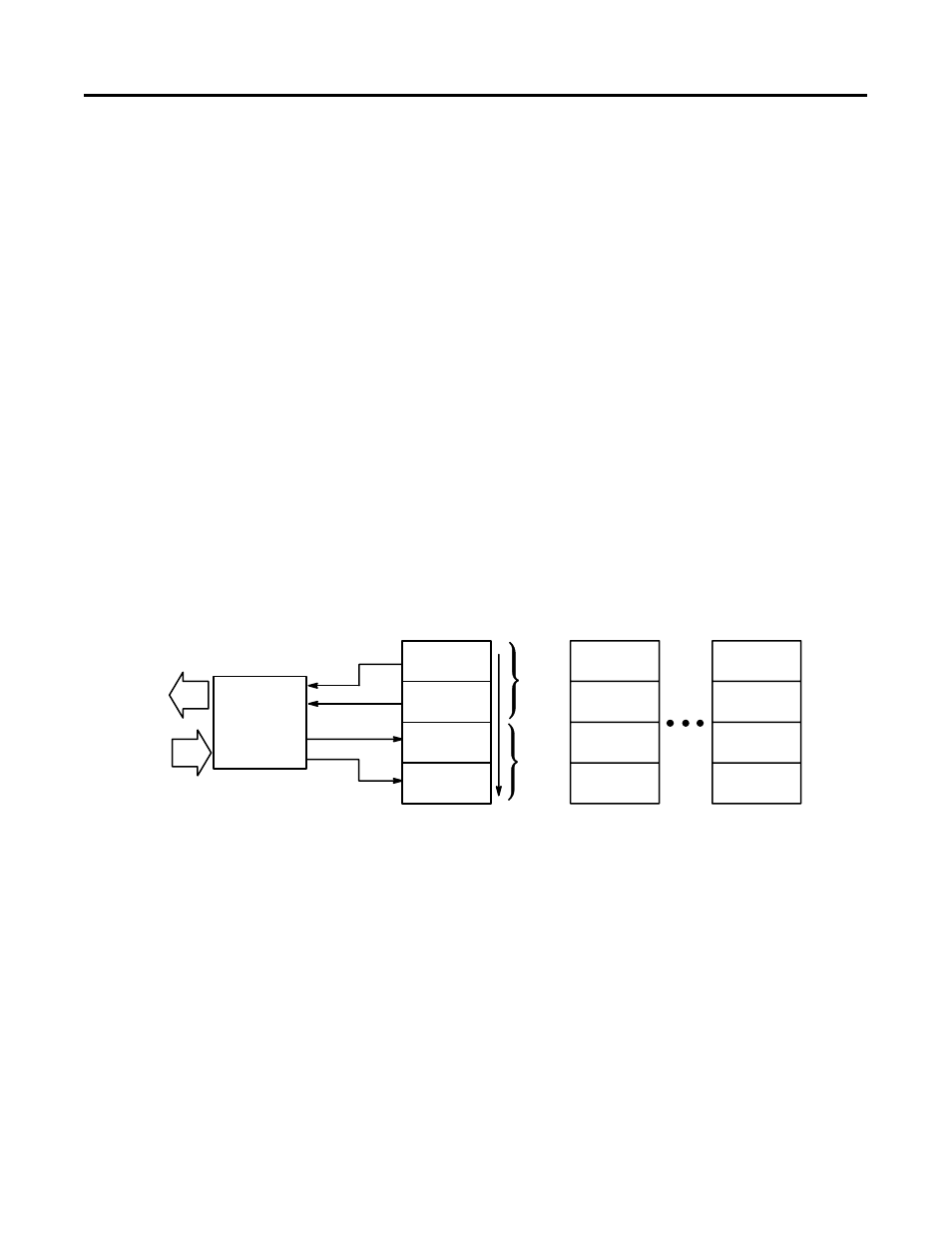
One 1798-ADN DeviceNet adapter can interface with up to eight
FlexArmor I/O modules placed in a FlexArmor baseplate. The adapter
communicates to other network system components (typically one or
more controllers or scanners, and/or programming terminals) over the
DeviceNet network. The adapter communicates with its I/O modules
over the backplane.
The I/O map for a module is divided into read words and write
words. Read words consist of input and status words and write words
consist of output and configuration words. The number of read words
or write words can be zero or more. The length of each I/O module’s
read words and write words varies in size depending on module
complexity. Each I/O module will support at least 1 input word or 1
output word. Status and configuration are optional, depending on the
module.
Network
I/O Module
I/O Module
I/O Module
Inputs
Inputs
Inputs
Status
Status
Status
Outputs
Outputs
Outputs
Configuration
Configuration
Configuration
Read
Write
DeviceNet
Adapter
Slot 0
Slot 1
Slot 7
Read
Words
Write
Words