Description of adapter input status word – Rockwell Automation 1798-IB4 FlexArmor User Manual User Manual
Page 17
Publication 1798-UM001B-EN-P - November 2002
How Communication Takes Place and I/O Image Table Mapping 2-3
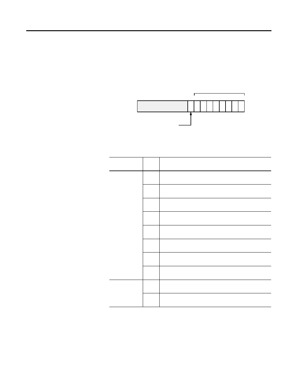
Description of Adapter Input Status Word
The input status word consists of:
•
I/O module fault bits - 1 status bit for each slot
•
node address changed - 1 bit
The adapter input status word bit descriptions are shown in the
following table.
Bit
Description
Bit
Explanation
I/O Module
Fault
0
This bit is set (1) when an error is detected in slot
position 0.
1
This bit is set (1) when an error is detected in slot
position 1.
2
This bit is set (1) when an error is detected in slot
position 2.
3
This bit is set (1) when an error is detected in slot
position 3.
4
This bit is set (1) when an error is detected in slot
position 4.
5
This bit is set (1) when an error is detected in slot
position 5.
6
This bit is set (1) when an error is detected in slot
position 6.
7
This bit is set (1) when an error is detected in slot
position 7.
Node Address
Changed
8
This bit is set (1) when the node address switch setting
has been changed since power up.
9 thru
15
Not used - sent as zeroes.
Not Used
I/O Module Fault Bits
Node Address Changed Bit
Sl
ot
7
Sl
ot
6
Sl
ot
5
Sl
ot
4
Sl
ot
3
Sl
ot
2
Sl
ot
1
Sl
ot
0
Bit: 15 9 through 15 8 7 6 5 4 3 2 1 0
42843