Devicenet adapter components, Power requirements, Diagnostic indicators – Rockwell Automation 1798-IB4 FlexArmor User Manual User Manual
Page 10
Publication 1798-UM001B-EN-P - November 2002
1-2 Install Your DeviceNet Adapter Module
For information on how communications occurs on the FlexArmor
system backplane, refer to Chapter 2.
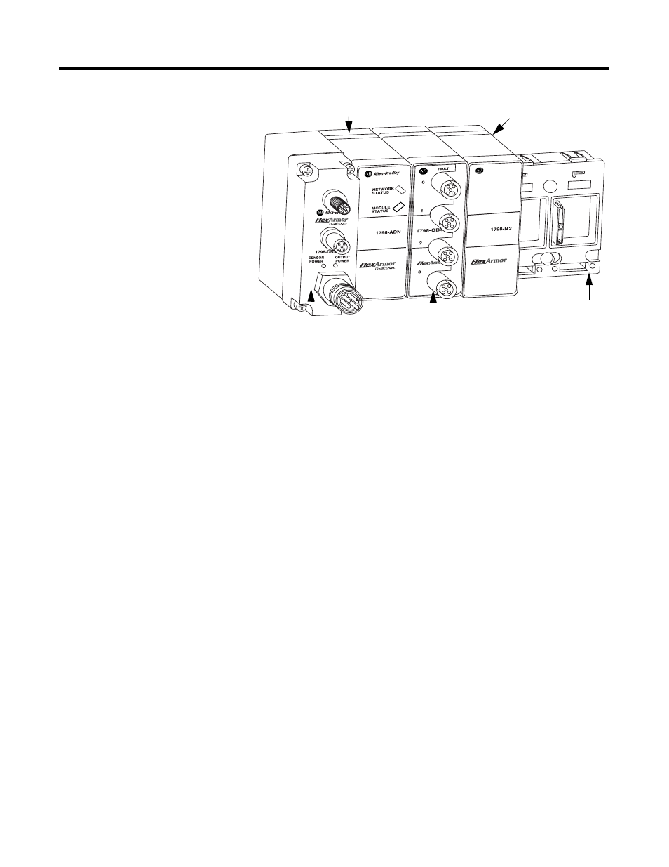
DeviceNet Adapter
Components
The adapter module consists of the following major components:
•
diagnostic indicators
•
node address switch
Diagnostic Indicators
Diagnostic indicators are located on the front panel of the adapter
module. They show both normal operation and error conditions in
your remote I/O system. The indicators are:
•
Mod/Net status
•
I/O status
A complete description of the diagnostic indicators and how to use
them for troubleshooting is explained in Chapter 4.
Power Requirements
The FlexArmor system requires a current of 400 mA at 24V dc from
the 1798-FTP sensor power connector for FLEX bus operation. This is
sufficient to support up to 8 modules. Remember to add this amount
to current requirements for other modules using the same 24V supply.
The FlexArmor system consumed 90 mA of DeviceNet power.
1798-0B4E
1798-BP4
4-position
Baseplate
FTP (Field Termination Plug)
1798-ADN
1798-N2
42537