Rockwell Automation 1798-IB4 FlexArmor User Manual User Manual
Page 22
Publication 1798-UM001B-EN-P - November 2002
2-8 How Communication Takes Place and I/O Image Table Mapping
Input Delay Times for the 1798-IB8 Input Module
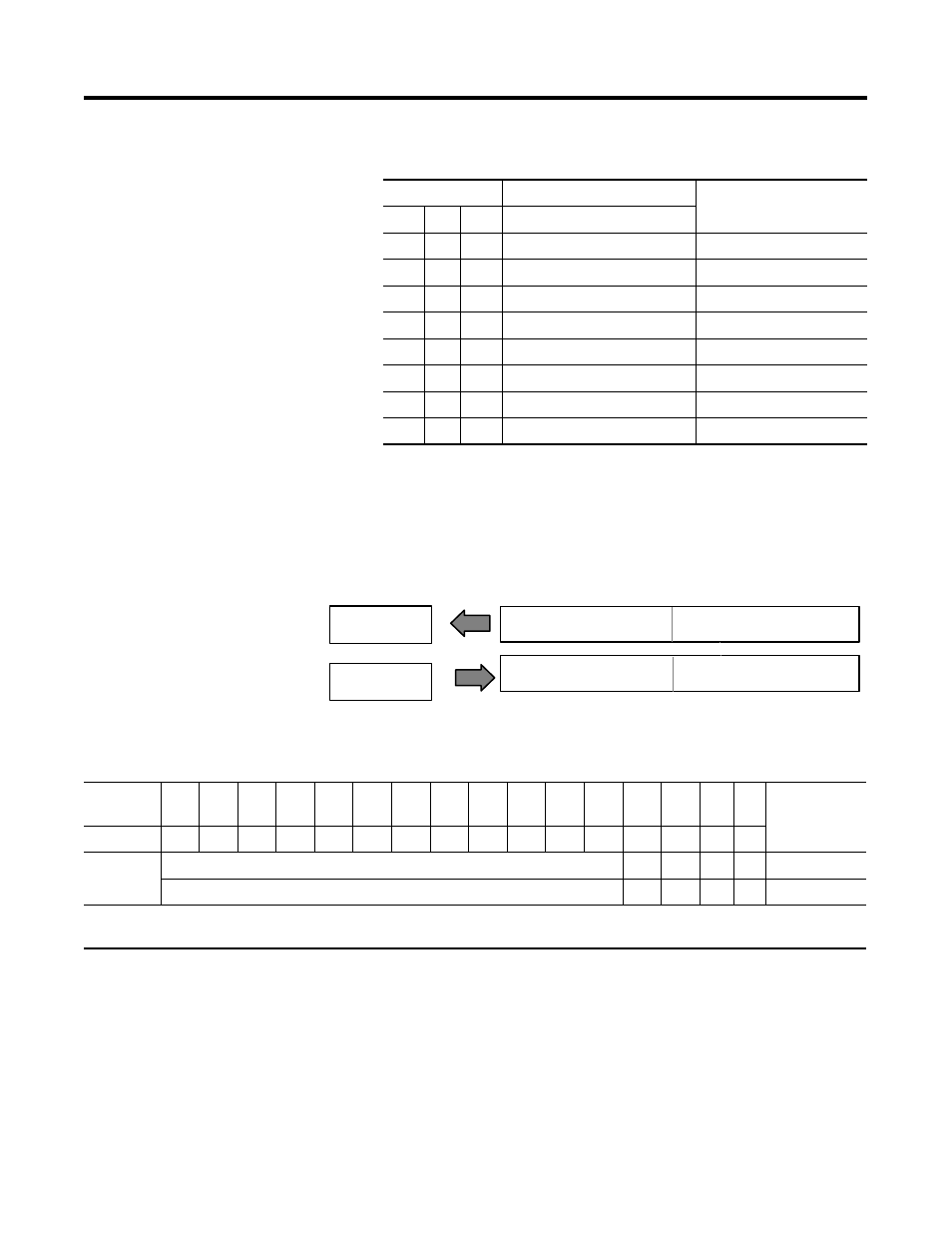
Description of 1798-OB4E Image Table Mapping
Memory Map of 4 Point Discrete Output Module Image Table - 1798-OB4E
Bits
Description
Selected Delay Time
02
01
00
Delay Time for Inputs 00-07
0
0
0
Delay Time 0 (default)
256µs
0
0
1
Delay Time 1
512µs
0
1
0
Delay Time 2
1ms
0
1
1
Delay Time 3
2ms
1
0
0
Delay Time 4
4ms
1
0
1
Delay Time 5
8ms
1
1
0
Delay Time 6
16ms
1
1
1
Delay Time 7
32ms
I/O Image
Input Size
Module Image
0 or 1 Word
1 Word
Read
Write
Output
Not Used
Fault Bits
Reserved
Outputs
42824
Decimal
Bit
15
14
13
12
11
10
09
08
07
06
05
04
03
02
01
00
Size
Octal Bit
17
16
15
14
13
12
11
10
07
06
05
04
03
02
01
00
Not used
F3
F2
F1
F0
Read Word 1
Reserved
O3
O2
O1
O0 Write Word 1
Where O = Output Value (O0 corresponds to output 0, O1 corresponds to output 1, etc.)
F0-F3 = Indicate the status of each output point (0=Output normal, 1=Output faulted)