Rockwell Automation 1798-IB4 FlexArmor User Manual User Manual
Page 20
Publication 1798-UM001B-EN-P - November 2002
2-6 How Communication Takes Place and I/O Image Table Mapping
Input Delay Times for the 1798-IB4 Input Module
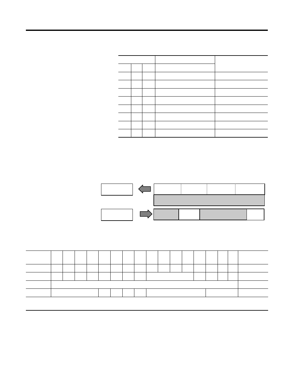
Description of 1798-IB4D Image Table Mapping
Memory Map of 4 Point Discrete Input Module Image Table - 1798-IB4D
Bits
Description
Selected Delay Time
02
01
00
Delay Time for Inputs 00-03
0
0
0
Delay Time 0 (default)
256µs
0
0
1
Delay Time 1
512µs
0
1
0
Delay Time 2
1ms
0
1
1
Delay Time 3
2ms
1
0
0
Delay Time 4
4ms
1
0
1
Delay Time 5
8ms
1
1
0
Delay Time 6
16ms
1
1
1
Delay Time 7
32ms
I/O Image
Input Size
Module Image
1 or 2 Words
0 or 1 Word
Read
Write
Output Size
Inputs
Delay
Time
Not used
Reserved
Open Wire
Disables
Reserved
Short Circuit
Detect
43388
Open Wire
Detect
Not Used
Decimal
Bit
15
14
13
12
11
10
09
08
07
06
05
04
03
02
01
00
Size
Octal Bit
17
16
15
14
13
12
11
10
07
06
05
04
03
02
01
00
Dec
S3
S2
S1
S0
W3
W2
W1
W0
Not Used
I3
I2
I1
I0
Read Word 1
Not Used
Read Word 2
Reserved
D3
D2
D1
D0
Reserved
DT 00-3
Write Word 1
Where I = Input Data (I0 corresponds to input 0, I1 corresponds to input 1, etc.); DT = Input Delay Time (DT 00-3
corresponds to inputs 0 through 3) W = Open Wire Detect; S = Short Circuit Detect; D = Open Wire Disable