Rockwell Automation 1794-OB16D FLEX I/O Diagnostic Modules User Manual User Manual
Page 50
Publication 1794-UM061A-EN-P - July 2006
48 Configure FLEX I/O Digital Modules on a DeviceNet Network
Add the Scanner to the I/O
Configuration of the
Controller Using RSLogix
5000 Software
To access the data of your network, add the scanner to the I/O configuration
of the controller.
To add a scanner:
If You Need to Conserve EtherNet/IP or ControlNet Network
Bandwidth
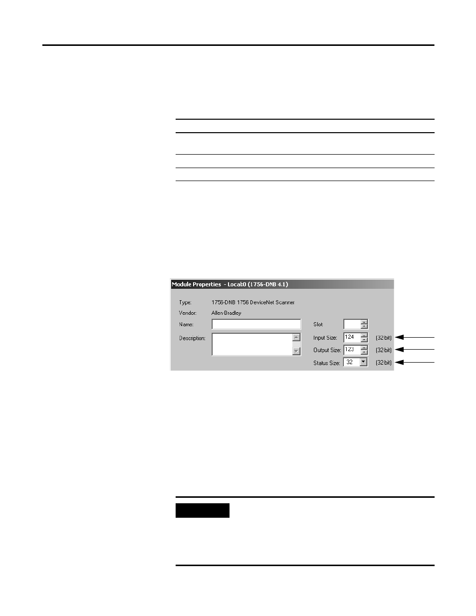
The default configuration of the scanner gives you the maximum amount of
input, output, and status data.
If the scanner communicates with the controller via an EtherNet/IP or
ControlNet network and you need to conserve bandwidth over that network,
consider reducing the input, output, or status sizes.
• Set the input and output sizes = the number of input and output DINTs
in the scanner that actually store device data.
• If you are
not
going to use all the status information, set the status size
to the minimum required. See Set the status size for a scanner on
page 49.
Step:
See page:
❑ If You Need to Conserve EtherNet/IP or ControlNet Network
❑ Add the Scanner to the I/O Configuration Folder
❑ Define the Properties of the Scanner
EXAMPLE
Set the status size for a scanner
• If you want to
only
use the ASCII representation of
scanner status/display, then set the Status Size = 10.
• If you also want to read the status code of the scanner,
set the Status Size = 11.