Rockwell Automation 1794-OB16D FLEX I/O Diagnostic Modules User Manual User Manual
Page 19
Publication 1794-UM061A-EN-P - July 2006
1794 FLEX I/O Diagnostic Digital Modules Overview
17
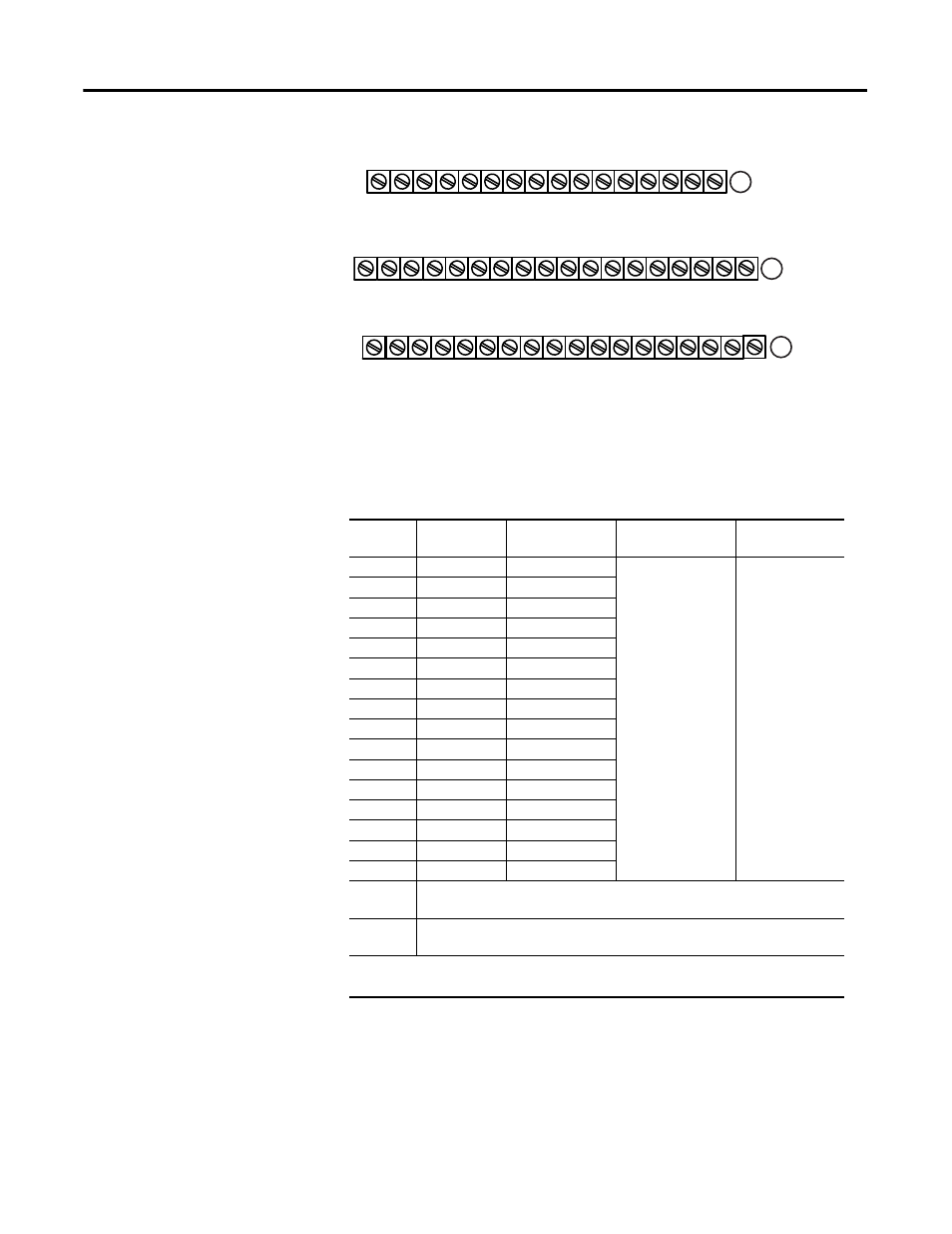
1794-TB32 and 1794-TB32S Terminal Base Wiring for the 1794-IB16D
Wiring for 1794-IB16D (use with 1794-TB32 or 1794-TB32S Terminal Base Units)
Input
Input
Terminal
Sensor Power
Terminal
Common
1
Supply
IN 00
A-0
B-17
-V common
connected to
terminals 36, 38,
40, 42, 44, 46, 48,
and 50
+V2 connected
to terminals 43,
45, 47, and 49
(+V1 terminals
35, 37, 39, and
41 are not used).
IN 01
A-1
B-18
IN 02
A-2
B-19
IN 03
A-3
B-20
IN 04
A-4
B-21
IN 05
A-5
B-22
IN 06
A-6
B-23
IN 07
A-7
B-24
IN 08
A-8
B-25
IN 09
A-9
B-26
IN 10
A-10
B-27
IN 11
A-11
B-28
IN 12
A-12
B-29
IN 13
A-13
B-30
IN 14
A-14
B-31
IN 15
A-15
B-32
+V2 dc
power
Power terminals 43, 45, 47, and 49 (power terminals are internally
connected together in the module)
COM dc
Return
Common terminals 36, 38, 40, 42, 44, 46, 48, and 50 (common terminals
COM 1 and COM 2 are internally connected together in the module)
(1)
3-wire devices only. 2-wire devices use input and sensor power terminals; 3-wire
devices use input, sensor power and common terminals.
17 18 19 20 21 22 23 24 25 26 27 28 29 30 31 32 33
0 1 2 3 4 5 6 7 8 9 10 11 12 13 14 15
16
35 36 37 38 39 40 41 42 43 44 45 46 47 48 49 50 51
34
NC
Inputs Channels 0-15
Sensor Power Terminals for Channels 0-15
+V1 COM1 +V1 COM1 +V1 COM1 +V1 COM1 +V2 COM2 +V2 COM2 +V2 COM2 +V2 COM2
NC
NC
NC
A
B
C
Sensor Common and User Power Common:
Terminals C-36, C-38, C-40, C-42, C-44, C-46, C-48 and C-50.
User power (+) Voltage: Terminals C-43, C-45, C-47 and C-49.
0 1 2 3 4 5 6 7 8 9 10 11 12 13 14 15
0 1 2 3 4 5 6 7 8 9 10 11 12 13 14 15
COM1 and COM2 are connected together in the module.
+V1 Terminals C-35, C-37, C-39, and C-41 are not used