Rockwell Automation 1794-OB16D FLEX I/O Diagnostic Modules User Manual User Manual
Page 20
18 1794 FLEX I/O Diagnostic Digital Modules Overview
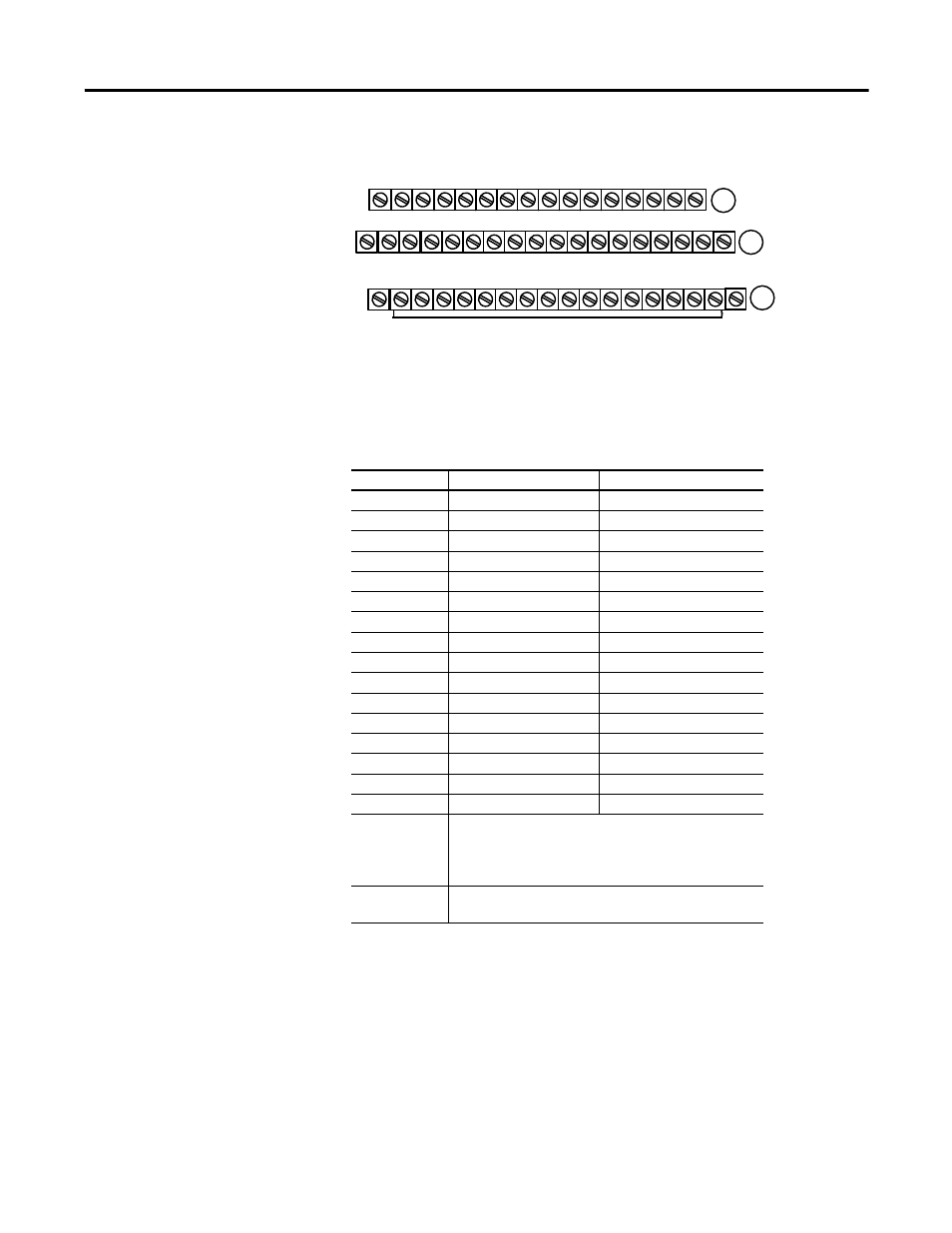
1794-TB2, -TB3, and -TB3S Terminal Base Wiring for the 1794-OB16D
Wiring Connections for the 1794-OB16D (use with 1794-TB2, 1794-TB3 or 1794-TB3S Terminal
Base Units)
.
Outputs
Output Terminal
Common Terminal
Output 00
A-0
B-17
Output 01
A-1
B-18
Output 02
A-2
B-19
Output 03
A-3
B-20
Output 04
A-4
B-21
Output 05
A-5
B-22
Output 06
A-6
B-23
Output 07
A-7
B-24
Output 08
A-8
B-25
Output 09
A-9
B-26
Output 10
A-10
B-27
Output 11
A-11
B-28
Output 12
A-12
B-29
Output 13
A-13
B-30
Output 14
A-14
B-31
Output 15
A-15
B-32
+V dc
C-34 and C-51 (1794-TB2) (Power Terminals are
internally connected in the terminal base unit.
C-34…C-51 (1794-TB3, 1794-TB3S) (Power terminals
are internally connected in the terminal base unit.
Common
B-16…B-33 (Common terminals are internally
connected in the terminal base unit.
17 18 19 20 21 22 23 24 25 26 27 28 29 30 31 32 33
0 1 2 3 4 5 6 7 8 9 10 11 12 13 14 15
35 36 37 38 39 40 41 42 43 44 45 46 47 48 49 50 51
34
Outputs
Commons
(1794-TB3 shown)
-V (Supply Common) = Terminals B-16 through B-33.
+V (Supply +Voltage In) = Terminals C-34 through C-51.
-V
Voltage
In +V
Voltage
Out +V
Voltage
A
B
C
(Use B-33 and C-51 for daisy-chaining to next terminal base unit.)
Common
-V
Common
Terminals 35 through 50 not available on 1794-TB2
16