Unused sensor power ports, Open contact mechanical switches and relays, Sensor power internal voltage drop – Rockwell Automation 1794-OB16D FLEX I/O Diagnostic Modules User Manual User Manual
Page 27
Publication 1794-UM061A-EN-P - July 2006
About the FLEX I/O Diagnostic Input Module
25
Unused Sensor Power Ports
You must connect dummy resistors to unused Sensor Power ports to mask the
diagnostic function. If external resistors are not used, the module's sensing
circuitry will not detect the intended voltage or current and not report that a
fault exists. The module’s fault and open-channel indicators light, and the
module’s open and module error bits are set, thus rendering fault detection of
the remaining channels useless. The recommended value of this dummy
resistor is 20 K
Ω
(+10%), 1/8 W (or larger).
Open Contact Mechanical Switches and Relays
The module's sensing circuitry must detect a minimum current level to
conclude that an open circuit does not exist. Electronic input field devices
typically have sufficient leakage current to satisfy the minimum requirement.
However, hard contacts have no leakage current, so you must add dummy
resistors in parallel to the hard contacts to supply the minimum current needed
for the module to sense that an open circuit does not exist. The
recommended resistor value is 20 k
Ω
(+10%), 1/8 W (or larger). Placement of
the dummy resistor at the field device also allows for monitoring of field
wiring conditions. Connect the resistor between sensor power and input signal,
or between sensor power and common.
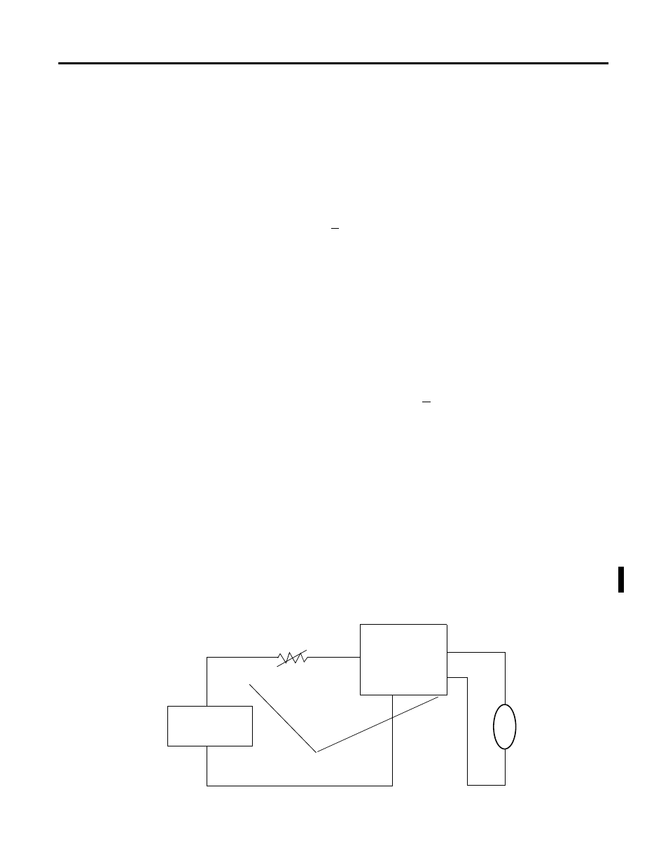
Sensor Power Internal Voltage Drop
The modules sensor power circuit exhibits an internal voltage drop. This
voltage drop can be as large as 2.2V for all operating conditions. You must
subtract 2.2V from the value of your external user power supply to determine
the voltage applied to power attached sensors. Make sure this voltage meets
sensor requirements. Consult the data sheet for your sensor to determine what
voltage is necessary.
User Power
+
PTC Resistor
Off-Wire
Current Monitor
Fault if:
1 < 50
μ
A
Sensor Power
Sensor
Input
Vsensor = (Ext Pwr) - 2.2V
Overcurrent causes PTC to open
Voltage Drop = 2.2V maximum
24V dc External
User Power Supply
User Power
-