Rockwell Automation 1771-QDC, D17716.5.85(Passport) MNL. PLASTIC MOLDING MODULE User Manual
Page 46
Enter Your SWTL Configuration Values Here
Configure the QDC Module's I/O
Chapter 3
3-15
ignores all profile commands (except set-outputs and jogs) until you jog
the cylinder back through the deadband into the safe zone at either end
The deadband guards against sensor noise flickering the SWTL alarms and
requires the operator to jog the cylinder a set distance away from the
software overtravel. We recommend a value of 00.10 inch as a starting
deadband. Your sensor may require a greater deadband.
ATTENTION: The QDC module ignores SWTL alarms when
jogging or when performing a set-output operation.
Configure the QDC module for SWTL as follows:
1.
Determine these SWTL values for ram (screw) travel with respect to
the range of physical travel.
SWTL deadband
Maximum SWTL
Minimum SWTL
2.
Record non-zero SWTL values on Worksheet 3-F. Zero values
disable the corresponding SWTLs.
ATTENTION: Leaving your SWTL settings at zero (MCC13
and 14), inhibits the QDC module from performing this safety
function.
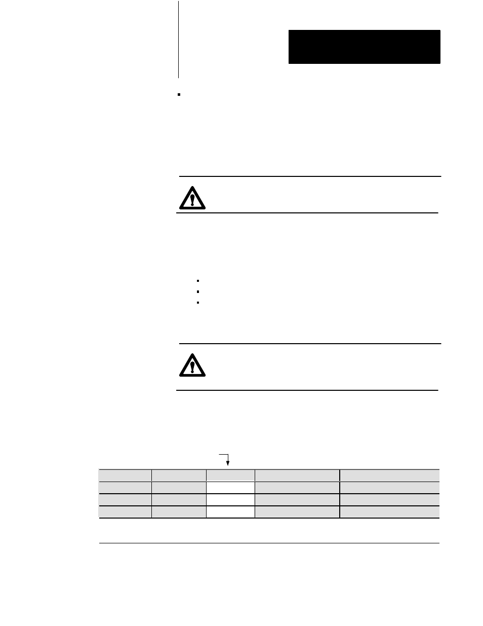
Worksheet 3ĆF
SWTL Configuration Values
Control Word
ProĆSet 600 Addr. Value
Description
Units
MCC13
N40:9
Screw Minimum SWTL
Screw Axis Measured from zero
1
MCC14
N40:10
Screw Maximum SWTL
Screw Axis Measured from zero
1
MCC15
N40:11
10
Screw SWTL Deadband
As noted
1
1
Incremental Distance
00.00 to 99.99in
000.0 to 999.9mm
You may now download your adjusted values using the MCC download
procedure presented earlier in this chapter.