Rockwell Automation 1771-QDC, D17716.5.85(Passport) MNL. PLASTIC MOLDING MODULE User Manual
Page 34
Select Input 1 (Screw Position) Range
Select Input 2 (Screw Pressure) Range
Select Input 3 (Screw RPM) Range
Select Input 4 (Cavity Pressure) Range
Input Range
0 - 10 vdc
0
0
1 - 5 vdc
0
1
4 - 20 mA
1
0
Not connected
1
1
Code:
Your value
Required initial value
loaded by ProĆSet 600
0 or 1
Select Output 1 Range
Select Output 2 Range
Select Output 3 Range
Select Output 4 Range
Output Range
-10 to +10 vdc
0
0
0 to +10 vdc
0
1
4 to 20 mA
1
0
Not connected
1
1
Code:
Your value
Required initial value
loaded by ProĆSet 600
0 or 1
Configure the QDC Module's I/O
Chapter 3
3-3
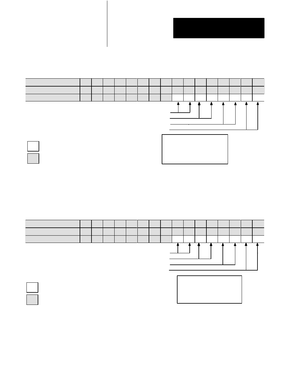
Worksheet 3ĆB
Select Input Ranges for your Sensors
Control Word MCC03ĆBxx
15
14 13 12 11
10
09 08 07 06 05 04 03 02 01 00
ProĆSet 600 Addr. B34/bit
559 558 557 556 555 554 553 552 551 550 549 548 547 546 545 544
Value
1
1
1
1
1
1
1
1
Example: If you select an input range of 4-20mA for all four inputs,
MCC03 = 11111111 10101010.
Worksheet 3ĆC
Select Output Ranges for your Valves
Control Word MCC04ĆBxx
15
14 13 12 11
10
09 08 07 06 05 04 03 02 01 00
ProĆSet 600 B34/bit
575 574 573 572 571 570 569 568 567 566 565 564 563 562 561 560
Value
1
1
1
1
1
1
1
1
Example: If you select 0-10 vdc for all four output ranges,
MCC04 = 11111111 01010101.
Important: Software input/output selections must match the jumper
settings for each respective input/output.