3ć14, Select optional configurations – Rockwell Automation 1771-QDC, D17716.5.85(Passport) MNL. PLASTIC MOLDING MODULE User Manual
Page 45
Configure the QDC Module's I/O
Chapter 3
3-14
8.
With your programming terminal, read the signal level returned in
SYS35 (N40:187) from your RPM sensor. You may wish to span
your RPM sensor at this time.
9.
Record this signal level on line 12 for MCC54.
10.
Release all flow and pressure from your screw motor and allow the
screw to return to rest.
You may now download your adjusted values to the QDC module using
the MCC download procedure presented earlier in this chapter.
You also have the option of configuring the following QDC features:
Use this Option:
For this Benefit:
Software Travel Limits
to guard against damaging the nozzle assembly or seals
Pressure Alarm Time Delay
to warn of excessive pressure without nuisance alarms
Digital Filter
to compensate for noise on position inputs
RPM Alarm Time Delay
to warn of excessive screw RPM without nuisance alarms
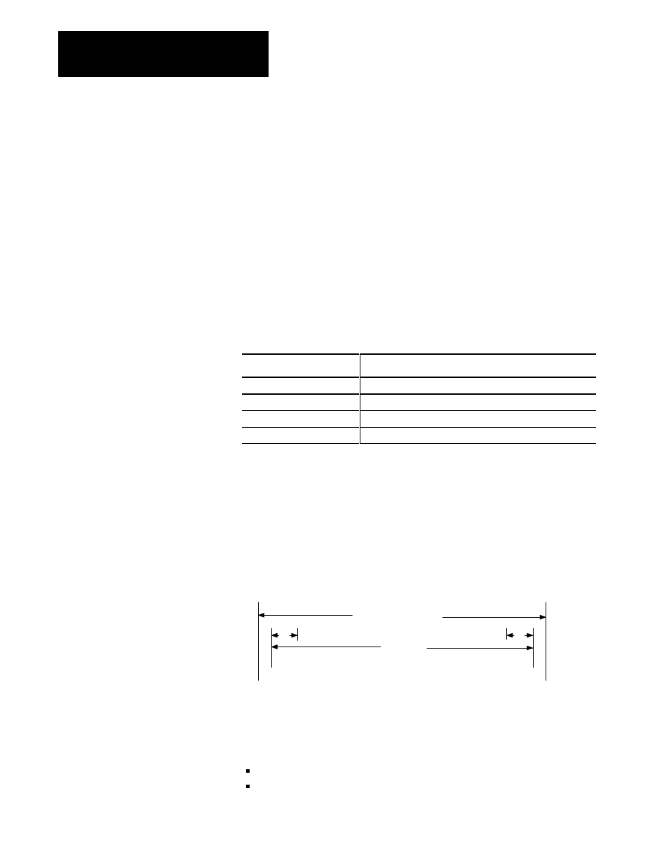
Configure Software Travel Limits
You may want to use the software restrictions to stop the travel of your ram
(screw) before it reaches its maximum limits (configured earlier in this
chapter).
Figure 4.1
Software Restrictions
Physical Travel Range
Min Position Max Position
d
d
Min SWTL Max SWTL
d = deadband
Safe Zone
During normal machine operation and whenever your cylinder travels
outside the safe zone (outside the specified software travel limits, SWTL),
the QDC module:
sets an alarm status bit
forces its outputs to zero
Select Optional
Configurations