Power supply tests (cont.) – Rockwell Automation 1560E SMC Flex Smart Motor Controller User Manual
Page 76
3-8
Commissioning Procedures
1560E-UM050B-EN-P - June 2013
Power Supply Tests (cont.)
NOTE: Systems with optional Pump Control or Soft Stop include
continuous gate drive power supplies (IGDPS); therefore, step 5 does not
apply.
5. Since the gate driver circuits normally receive power from the snubber
circuits when the SMC is operating, an alternate source must be used
for testing. Locate the Portable Test Power Supply that was included
with the equipment, and verify that the rating corresponds to the
available power system (i.e. 110/120 VAC or 220/240 VAC). Plug the
unit into the power source, and plug the green connector into TB1 on
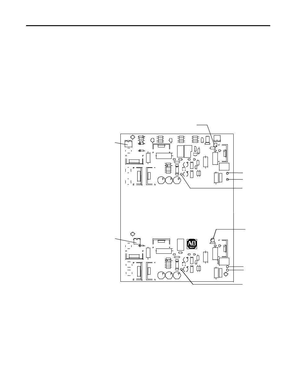
each of the gate driver sections (See Figure 3.4).
Yellow LED
Plug in test
power supply
(TB1)
Yellow LED
Plug in test
power supply
(TB1)
TP2 (+)
TP1 (Com)
TP7 (Gate)
TP7 (Gate)
TP1 (Com)
TP2 (+)
Yellow LED
Plug in test
power supply
(TB1)
Yellow LED
Plug in test
power supply
(TB1)
TP2 (+)
TP1 (Com)
TP7 (Gate)
TP7 (Gate)
TP1 (Com)
TP2 (+)
Figure 3.4 – Test Power Application on Gate Driver Board
6. The yellow LED on the upper right-hand side of the energized gate
driver circuit should be lit (it may appear dim, depending on ambient
light conditions). This is normally sufficient to verify that the gate drive
system is functioning, however, a more detailed check can be made
utilizing steps 7 and 8.