Fault display explanation – Rockwell Automation 1560E SMC Flex Smart Motor Controller User Manual
Page 121
Troubleshooting
9-3
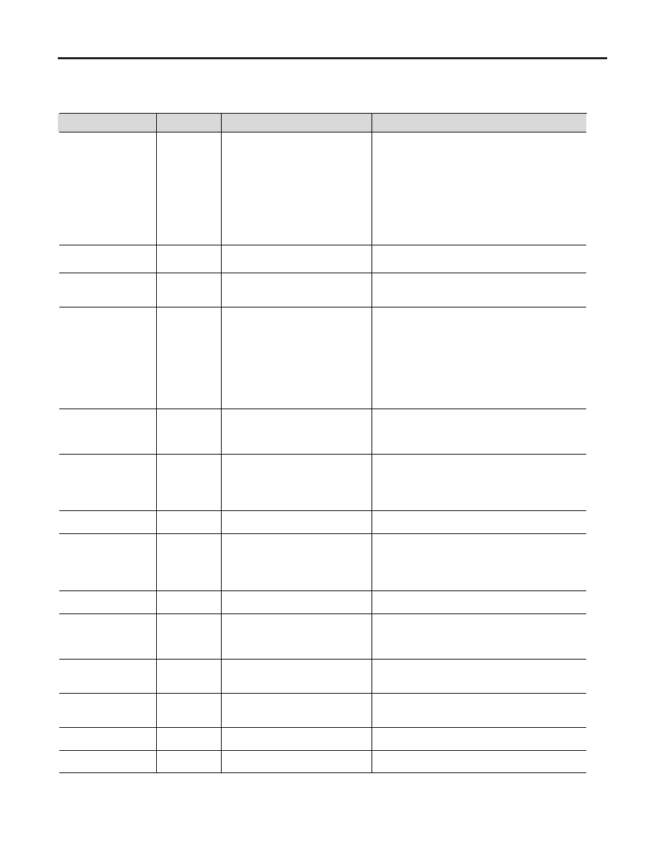
Table 9.A – Fault Display Explanation
Display
Fault Code
Possible Causes
Possible Solutions
Line Loss
:
(with phase indication)
1, 2, 3, 41, 42
and 43
• Missing supply phase
• Motor not connected properly
• Improper or missing feedback
• Check for open line (eg. blown line fuse)
• Check for open load lead
• Check current transformer connections and module
programming
• Check voltage sensing board connections and module
programming
• Check ribbon cable connections between Interface
Board and Control Module
• Check voltage feedback circuits
• Consult factory
Shorted SCR
4, 5 and 6
• Shorted Power Module
• Check for shorted SCR, replace if necessary
(See Power Circuit Troubleshooting)
Open Gate
(with phase indication)
7, 8 and 9
• Open gate circuitry
• Loose gate lead
• Perform power supply tests (Chapter 3)
• Check gate lead connections to the gate driver boards
and fiber optics
PTC Power Pole
10
• Controller ventilation blocked
• Controller duty cycle exceeded
• Fan failure
• Ambient temperature limit exceeded
• Failed thermistor
• Failed control module
• Failed gate driver board
• Failed fiber optic cable
• Failed interface board
• Check for proper ventilation
• Check application duty cycle
• Replace fan
• Wait for controller to cool or provide external cooling
• Check connection or replace thermistor
• Replace control module
• Test or replace gate driver board
• Test or replace cable
• Test or replace interface board; check ribbon cables
Motor PTC
12
• Motor ventilation blocked
• Motor duty cycle exceeded
• PTC open
• Check for proper ventilation
• Check application duty cycle
• Wait for motor to cool or provide external cooling
• Check resistance of PTC
Open Bypass
13, 14, 15
• Control voltage is low
• Inoperable bypass contactor
• IntelliVAC fault
• Check control voltage power supply
• Check control circuit operation
• Check control plug on contactor
• Check status of IntelliVAC, correct the condition, reset
the module
No load
16, 17, 18, 40
• Loss of load side power wiring
• Loss of feedback
• Check all load side power connections and motor windings
• Check voltage sensing module
Line Unbalance
19
• Supply unbalance is greater than
the user-programmed value
• The delay time is too short for the
application
• Unbalanced feedback
• Check power system and correct if necessary
• Extend the delay time to match the application
requirements
• Check voltage sensing module
Overvoltage
20
• Supply voltage is greater than user-
programmed value
• Check power system and correct if necessary
• Correct the user-programmed value
Undervoltage
21
• Supply voltage is less than user-
programmed value
• The delay time is too short for the
application
• Check power system and correct if necessary
• Correct the user-programmed value
• Extend the delay time to match the application
requirements.
Overload
22
• Motor overloaded
• Overload parameters are not
matched to the motor
• Check motor overload condition
• Check programmed values for overload class and
motor FLC
Underload
23
• Broken motor shaft
• Broken belts, toolbits, etc.
• Pump cavitation
• Repair or replace motor
• Check machine
• Check pump system
Jam
24
• Motor current has exceeded the
user programmed jam level
• Correct source of jam
• Check programmed time value
Stall
25
• Motor has not reached full speed by
the end of the programmed ramp time
• Correct source of stall
: Prestart fault indication