Control terminal designations – Rockwell Automation 1560E SMC Flex Smart Motor Controller User Manual
Page 68
2-20
Installation
% 5-" %. 0
Control Terminal Designations
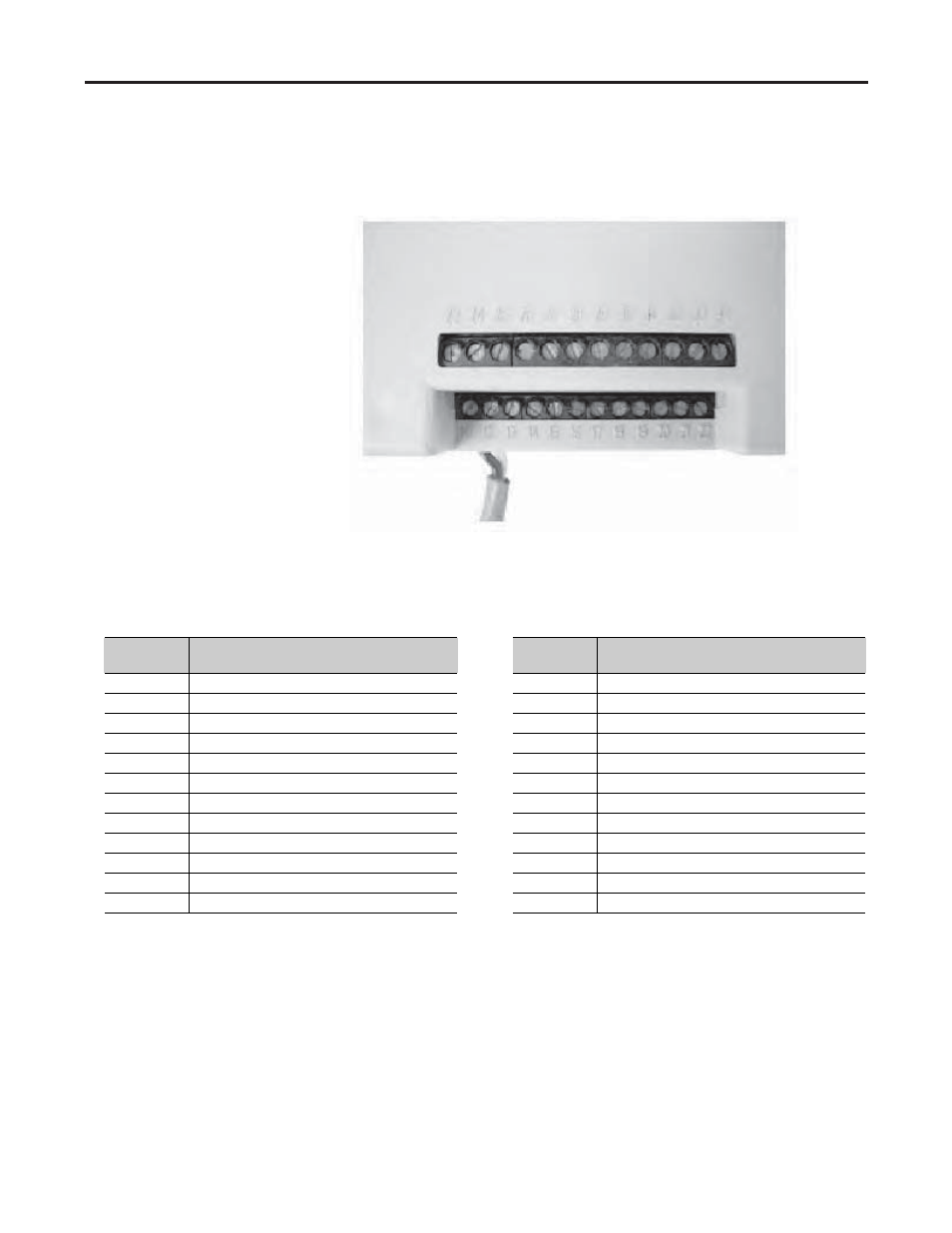
As shown in Figure 2.10, the SMC-Flex controller contains 24 control
terminals on the front of the controller.
Figure 2.10 – SMC-Flex Controller Control Terminals
Terminal
Number
Description
Terminal
Number
Description
11
Control Power Input
23
PTC Input
:
12
Control Power Common
24
PTC Input
:
13
Control Enable Input
:
25
Tach Input ( - )
14
Control Module Ground
26
Tach Input ( + )
15
Option Input #2
:
27
Ground Fault Transformer Input
:
16
Option Input #1
:
28
Ground Fault Transformer Input
:
17
Start Input
:
29
Fault Contact (N.O./N.C.) ➍
18
Stop Input
:
30
Fault Contact (N.O./N.C.) ➍
19
N.O. Aux. Contact #1 (Up-to-Speed)
; ➍
31
Alarm Contact (N.O./N.C.) ➍
20
N.O. Aux. Contact #1 (Up-to-Speed)
; ➍
32
Alarm Contact (N.O./N.C.) ➍
21
Not Used
33
Aux. Contact #2 (Normal) (N.O./N.C.) ➌ ➍
22
Not Used
34
Aux. Contact #2 (Normal) (N.O./N.C.) ➌ ➍
:
Do not connect any additional loads to these terminals. These “parasitic” loads may cause problems with operation,
which may result in false starting and stopping.
;
Aux. Contact #1 is always programmed for Up-to-Speed to control the bypass contactor in MV applications.
➌
Aux. Contact #2 is always programmed for “Normal” indication in MV applications.
➍
RC snubbers are required on inductive loads connected to auxiliary.
Note: The OFF state leakage current for a solid-state device connected to an SMC-Flex input must be less than 6 mA.