Input interlock mode, Figure 9 - controller wiring diagram – Rockwell Automation 1413-CAP-ME-PE Capacitor Bank Controller, Series C User Manual
Page 57
Rockwell Automation Publication 1413-UM001D-EN-P - November 2010
57
Operation Chapter 4
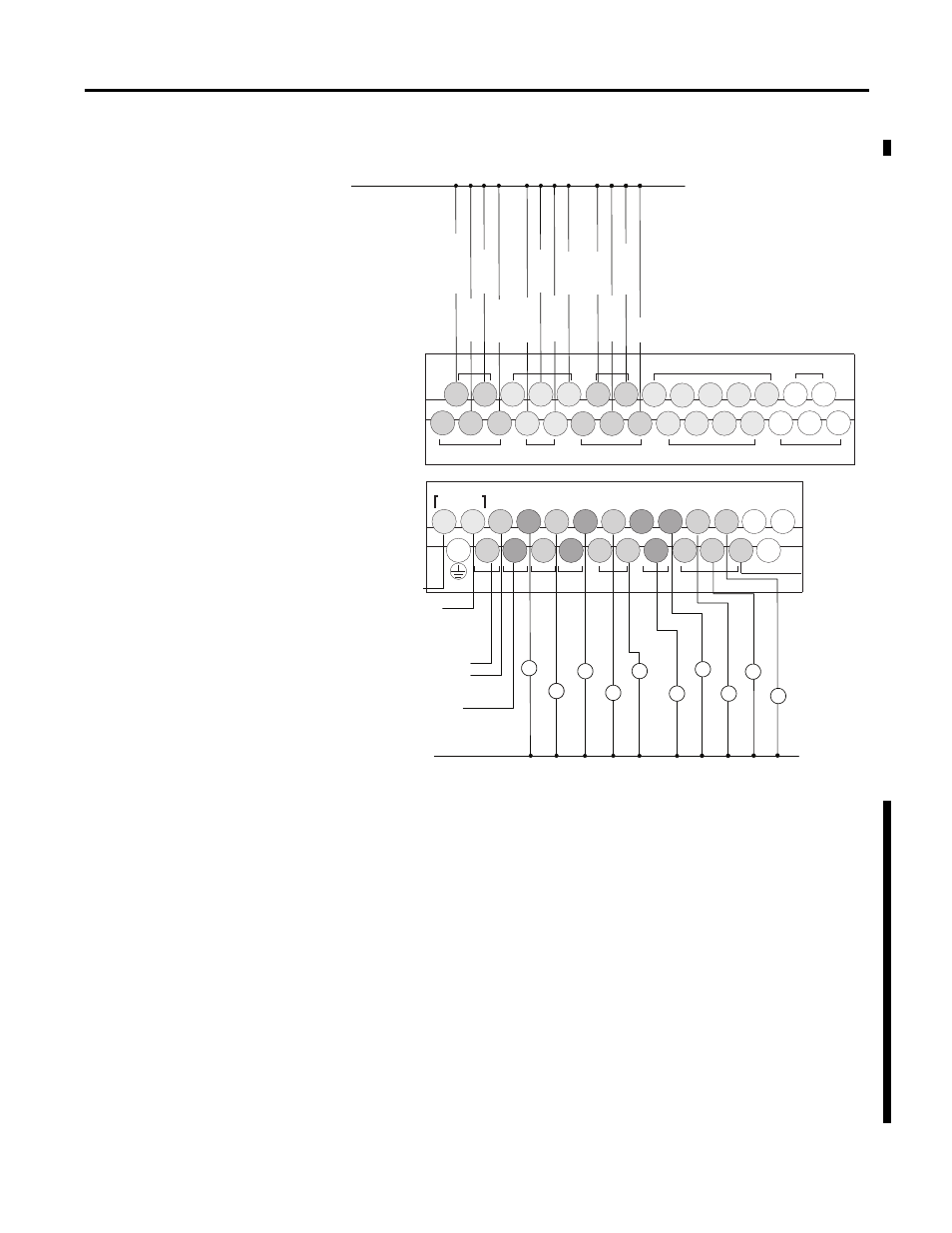
Figure 9 - Controller Wiring Diagram
Input Interlock Mode
The Input Interlock mode allows fault protection for each capacitor step through
the use of fault-protection relays. Wire normally closed fault-protection relays to
each input from 0…10 of the controller. Wire a normally-open momentary
pushbutton to Input 11. This pushbutton serves as a reset button.
During a fault occurrence, the controller discharges and locks-out the respective
capacitor step associated with the fault relay that tripped. The fault-protection
relay wired to Input 0 discharges and locks-out all capacitor steps. The remaining
fault-protection relays discharge and lock-out their respective capacitor step (that
is, Input 1 discharges and locks-out capacitor step 1).
In order to place a capacitor step back into the sequence, a fault must not be
present for that step, and a reset must be initiated by pushing the Reset
pushbutton.
Ground
33
Capacitor Step Contactors or Interposing Relays
Capacitor Step Contactors or Interposing Relays
2
4
5
6
7
8
9
10
1
Spare Output
120V AC
Control
Power
Fault Relay 1
Fault Relay 2
Fault Relay 3
Fault Relay 4
Fault Relay 5
Fault Relay 6
Fault Relay 7
Fault Relay 8
Fault Relay 9
Fault Relay 10
Reset
Master Fault Relay
Inputs
Outputs
Isolated Alarm Output
Capacitor Step
Control Power
COM 1
IV1(+)
IV3(+)
IN5
IN7
IN4
IN6
COM 2
IN8
IN10
IN9
IN11
COM 3
IN13
IN15
IN17
IN19
IN12
IN14
IN16
IN18
COM
ANA
L1
OV1
OUT0
OUT1
OUT2
OUT3
OUT4
OUT5
OUT7
OUT8
OUT10
OUT6
OUT9
OUT11
OV0
VAC
L2/N
VAC
DC1
VAC
DC2
VAC
DC3
VAC
DC4
VAC
DC6
VAC
COM
ANA
DC5
VAC
Group 0
Group 1 Group 2
Group 3
Group 5
Group 4
Group 6
COM 0
IN1
IN3
IN0
IN2
IV0(+)
IV2(+)
DC0
VAC