Rockwell Automation 1413-CAP-ME-PE Capacitor Bank Controller, Series C User Manual
Page 50
50
Rockwell Automation Publication 1413-UM001D-EN-P - November 2010
Chapter 3 Configuration
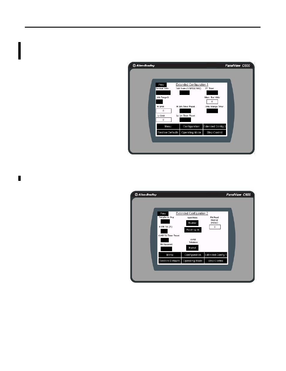
9.
Navigate to Menu then to Extended Configuration 1.
This screen operates in the same way as the initial configuration screen.
10.
Press Extended Config 2 to navigate to the Extended Configuration 2
screen from the Extended Configuration 1 screen.
These guidelines apply in the Configuration
screen:
• Nominal Volts is a number between 0 and
9999 using the scale
1/10/100/1000. Therefore, a voltage of
13,400V would be entered as 1340.
• Volt Range % is used for voltage high/low
alarms.
• Timer preset is for high and low values for
the high/low voltage alarms.
• PF timer is used to generate alarm if
Powerfactor is not achieve in that time.
TIP
All timers are in seconds.
These guidelines apply in the Configuration screen:
• The Samples to Avg number is between 5
and 10.
• The kVAR tolerance % of each capacitor to
trigger alarming.
• Input mode is disabled by default. If you are
using fault relays for respective steps, we
recommend that you use Input mode. Reset
inputs will clear controller alarms.
TIP
The leading kVAR limit allowed for the system, before the controller acts
to correct lead, typically is 33% of smallest capacitor step. The lagging
kVAR limit allowed for the system, before the controller acts to correct
lag, typically is 66% of largest capacitor step.