Default screen – Rockwell Automation 1413-CAP-ME-PE Capacitor Bank Controller, Series C User Manual
Page 46
46
Rockwell Automation Publication 1413-UM001D-EN-P - November 2010
Chapter 3 Configuration
Default Screen
The PowerMonitor 1000 unit lets you select and navigate to a default screen. The
default screen displays at startup and is displayed after the display has been
dormant for approximately 30 minutes. To set the current screen as the default,
press Enter and click Yes. If you’re in another menu and want to get back to the
default screen, continue pressing Escape until you are prompted To Default
Screen? Click Yes to display the default screen.
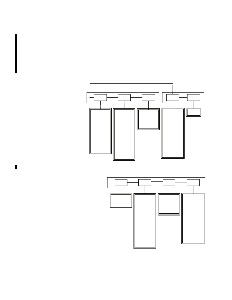
Figure 7 - Main Menu, Page 2
Figure 8 - Setup Submenu
Level 2
Level 3
Display Wiring
Diagnostics
Display Run
Status
Display I/O
Status
Program
Commands
Program
Setup
See Setup
Submenu
Clear kWh Registers
Clear kVARh Registers
Clear kVAh Registers
Clear Energy All
Registers
Clear Status 1 Count
Clear Status 2 Count
Force KYZ On
Force KYZ Off
Remove KYZ Force
Restore Defaults
Test Wiring Connections
Reset System
Clear Min/Max Log
Perform Wiring Diagram
Store Load Factor
Record
Clear Load Factor Log
Store TOU Record
Clear TOU Log
Troubleshooting Password
Date
Time
KYZ Status
S1 Status
S1 Status Count
S2 Status
S2 Status Count
Output Word
Series Number
Catalog Number
Comm Type
WIN Number
Application FRN
Boot Code FRN
Default Device ID
Accuracy Class
Overall Status
Flash Memory
SRAM Memory
NVRAM Memory
SPI Interface
Real Time Clock
Watchdog Timer
Metering Status
LCD Interface
Serial Interface
Ethernet Interface
Input Over Range
Phase Loss Detection
Terminals Locked
Wiring Status
Volts Input Missing
Volts Input Inverted
Amps Input Missing
Amps Input Inverted
Voltage Rotation
Amps ROtation
VOlts Ph1 Angle
Volts Ph1 Magnitude
Volts Ph2 Angle
Volts Ph2 Magnitude
Volts Ph3 Angle
Volts Ph3 Magnitude
Amps Ph1 Angle
Amps Ph1 Magnitude
Amps Ph2 Angle
Amps Ph2 Magnitude
Amps Ph3 Angle
Amps Ph3 Magnitude
Level 2 Program Mode, Level 3 Display Mode
Level 3, 4
Configuration Mode
Analog Input
Advanced
RS485
Ethernet
IP Address Byte a
IP Address Byte b
IP Address Byte c
IP Address Byte d
Subnet Mask Byte a
Subnet Mask Byte b
Subnet Mask Byte c
Subnet Mask Byte d
Gateway Byte a
Gateway Byte b
Gateway Byte c
Gateway Byte d
SNTP Mode Select
SNTP Update Rate
SNTP Time Zone
Time Server Byte a
Time Server Byte b
Time Server Byte c
Time Server Byte d
Broadcast Mode
Broadcast Port
Protocol Setting
Serial Delay mS
Baud Rate
Serial Address
Serial Data Format
Inter Character
Timeout
Max Node Address
New Password
Date
Time
Meter Averaging
DST Enable
DST Start
Month, Wk, Day
DST Start Hour
DST End
Month, Wk, Day
DST End Hour
KYZ Output Select
KYZ Output Scale
KYZ Pulse Duration
Status 1 Input Scale
Status 2 Input Scale
Demand Source
Demand Length
Demand Periods
Demand Sync Delay
Unit Error Action
Error Log Full Action
LCD Display Contrast
Voltage Mode
PT Primary
PT Secondary
CT Primary
System PF Setting