Rockwell Automation 1413-CAP-ME-PE Capacitor Bank Controller, Series C User Manual
Page 48
48
Rockwell Automation Publication 1413-UM001D-EN-P - November 2010
Chapter 3 Configuration
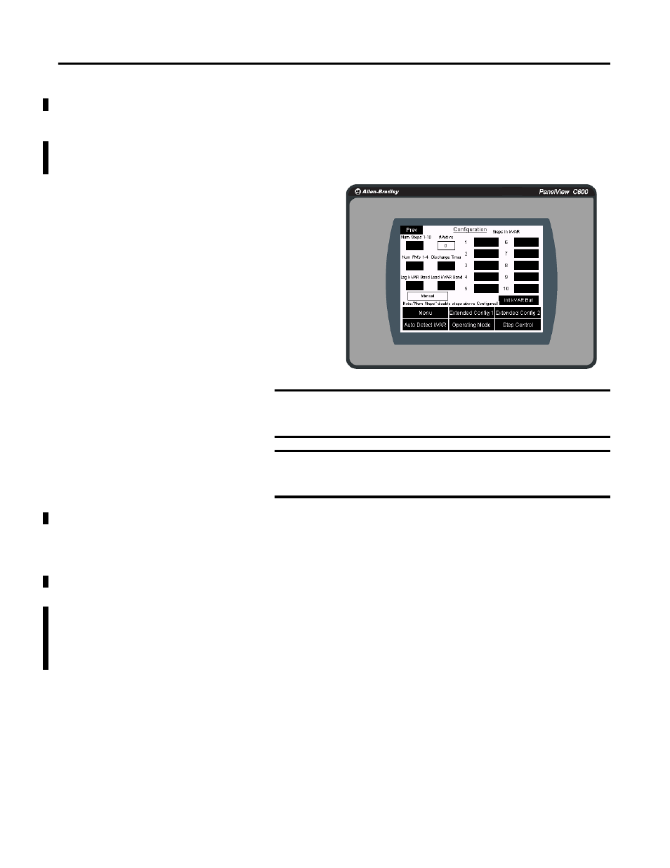
Configure the capacitor bank controller by using the optional PanelView
terminal.
1.
Press Menu to view the Menu from the Overview screen.
2.
Press Configuration to view the Configuration screen from the Menu.
3.
To edit a value, touch the desired field and the keypad appears.
4.
Enter the desired value by using the keypad and press Enter to store the
new value.
Pressing ESC cancels a change.
In this screen you can configure:
• the number of steps. The default value is 10; that will
show all 10 steps. Num Step is between 1 and 10.
• Number of PowerMonitors from 1…4. Default is 1.
At least one PowerMonitor unit must be configured.
• Steps in kVAR. This is the size of each capacitor.
Step 1 is wired to Output 1 (Capacitor Bank step 1
contact) of the MicroLogix controller and step 10 is
wired to output 10 (Capacitor Bank step 10 contact).
IMPORTANT
Stages and/or sizes of the Capacitor Bank typically require a
Power Quality study. The Capacitor Bank modes are Manual, FILO,
Balanced, and Best Fit.
IMPORTANT
For Discharge Time, check with the Capacitor Bank vendor for the
appropriate value. One discharge Capacitor Bank value applies to
all capacitor steps.
TIP
This Auto Detect kVAR feature is used in the commissioning phase. It is
recommended that the only load is the capacitor bank while using this
feature. It may require physically installing the current transformers only
for the capacitors. After running this feature, install your Current
Transformers to your power side.