Rockwell Automation 1413-CAP-ME-PE Capacitor Bank Controller, Series C User Manual
Page 16
16
Rockwell Automation Publication 1413-UM001D-EN-P - November 2010
Chapter 2 Installation
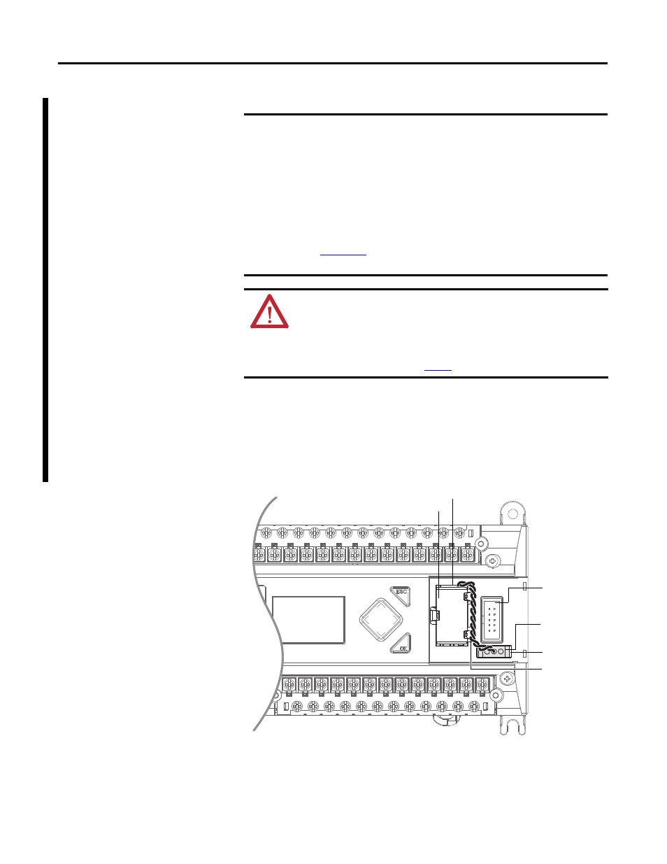
Follow these steps to connect the replaceable battery.
1.
Insert the replaceable battery wire connector into the controller’s battery
connector.
2.
Secure the battery connector wires so that it does not block the 1762
expansion bus connector as shown below.
IMPORTANT
The MicroLogix 1400 controller ships with the battery wire connector
connected.
Be sure that the battery wire connector is inserted into the connector port
if your application needs battery power. For example, when using a real-
time clock (RTC).
Replacing the battery when the controller is powered down will lose all
user application memory. Replace the battery when the controller is
powered on.
Refer to the SLC 500 Lithium Battery Installation Instructions, publication
, for more information on installation, handling, usage,
storage, and disposal of the battery.
WARNING: When you connect or disconnect the battery an electrical arc
can occur. This could cause an explosion in hazardous location
installations. Be sure that the area is nonhazardous before proceeding.
For Safety information on the handling of lithium batteries, including
handling and disposal of leaking batteries, see Guidelines for Handling
Lithium Batteries, public
.
1762 I/O
Expansion Bus
Connector
Battery Wires
Twisted Pair
Battery
Battery Wire
Connector
Battery
Connector
Battery Compartment