Step 4 – closing the front of the plenum sections, Step 5 – extension and elbow assembly – Rockwell Automation 1512B MV Controllers, 200/400A Two-High Cabinet, Standard and Arc-Resistant Enclosure User Manual
Page 91
Rockwell Automation Publication 1500-UM055G-EN-P - May 2013
83
ArcShield Plenum Installation Instructions
Appendix
B
The “End Cover Plate” must be mounted on the closed end of the Line-up at this
time during the assembly using 5/16-in. hardware (see
Left side).
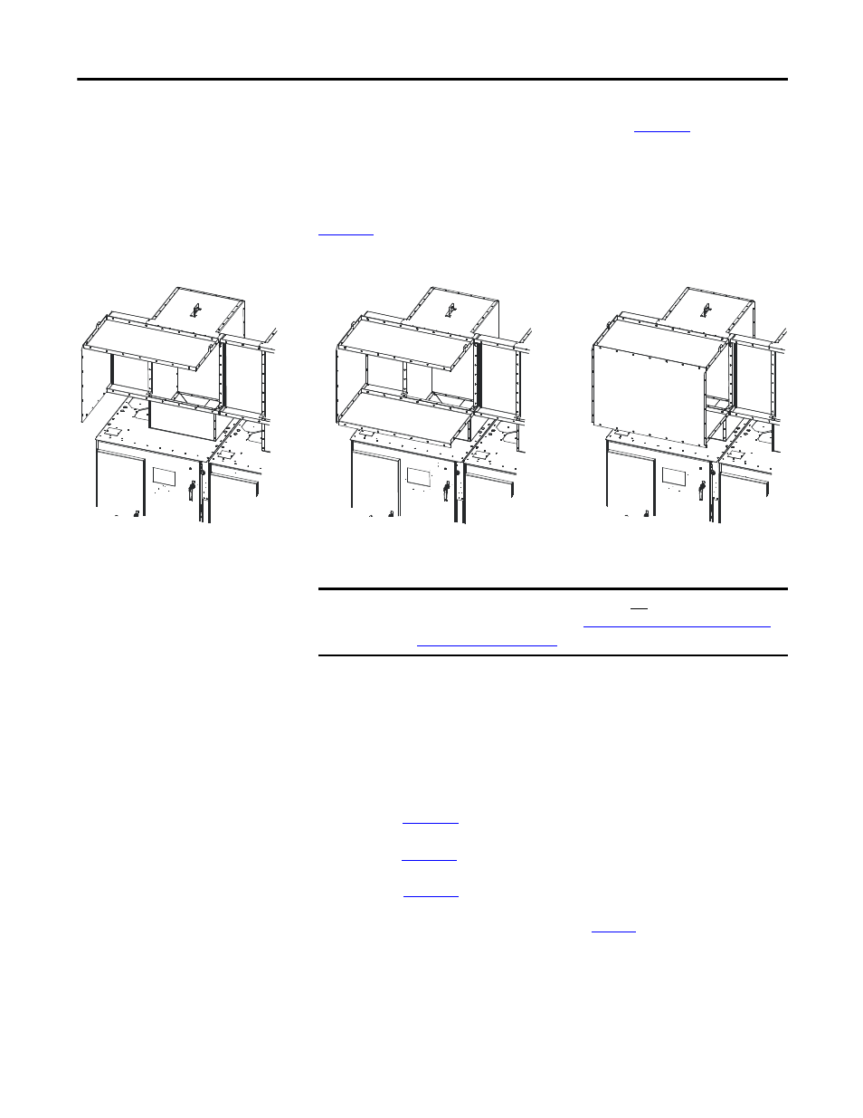
STEP 4 – Closing the Front of
the Plenum Sections
After the first stage of the Plenum assemblies have been mounted, the Plenums
can then be “closed-up” by replacing the front duct sections as shown in
.
Figure 83 - Plenum Sections
STEP 5 – Extension and Elbow
Assembly
The 36" Extension components and 90° Elbow Section are to be attached using
5/16-in. hardware in the following sequence:
Step 5B – See
Top Plate
Bottom Plate
Front Closing P
late
IMPORTANT
Do not re-install the front duct section of the last Plenum on the exhaust side
of the Line-up at this time (refer to
STEP 6 – Mounting Extension/Elbow to
for more information).
TIP
Use silicone caulking generously to fill any air gaps once the Plenum has been
securely mounted in place.
TIP