Top exiting load cables – Rockwell Automation 1512B MV Controllers, 200/400A Two-High Cabinet, Standard and Arc-Resistant Enclosure User Manual
Page 41
Rockwell Automation Publication 1500-UM055G-EN-P - May 2013
33
Installation – Arc-Resistant Enclosure (ArcShield)
Chapter 3
4. Remove the appropriate load cable conduit openings in the top or bottom
of the cabinet (see
Top Exiting Load Cables
5. Load cables for the bottom power cell should be routed first. Pull the
cables into the cabinet through the appropriate opening (see
).
Run the cables behind the current transformer mounting plate and into
the bottom power cell.
6. For the top power cell, pull the cables into the cabinet through the
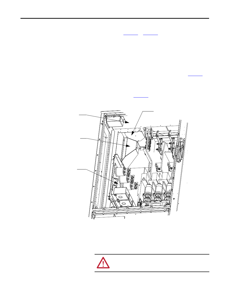
Figure 36 - Load Cable Conduit Openings
7. Connect the cables to the current transformers and tighten the
connections to 65 N•m (48 lb•ft).
8. Connect cable shields to the ground lug.
9. Reinstall the cable duct boot and reassemble the cabinet.
TIP
Follow steps 1-4 from previous section.
Top of Cabinet
Load Cable Conduit Opening for
Cables from Top Power Cell
Load Cable Conduit
Opening for Cables from
Bottom Power Cell
Current Transformer
Mounting Plate
ATTENTION: Ensure all barriers are replaced before re-energizing the
equipment. Failure to do so may result in electrical faults and cause
damage to equipment or serious injury to personnel.