Joining sections, Figure 5 – Rockwell Automation 1512B MV Controllers, 200/400A Two-High Cabinet, Standard and Arc-Resistant Enclosure User Manual
Page 16
8
Rockwell Automation Publication 1500-UM055G-EN-P - May 2013
Chapter 2
Installation – Standard Enclosure
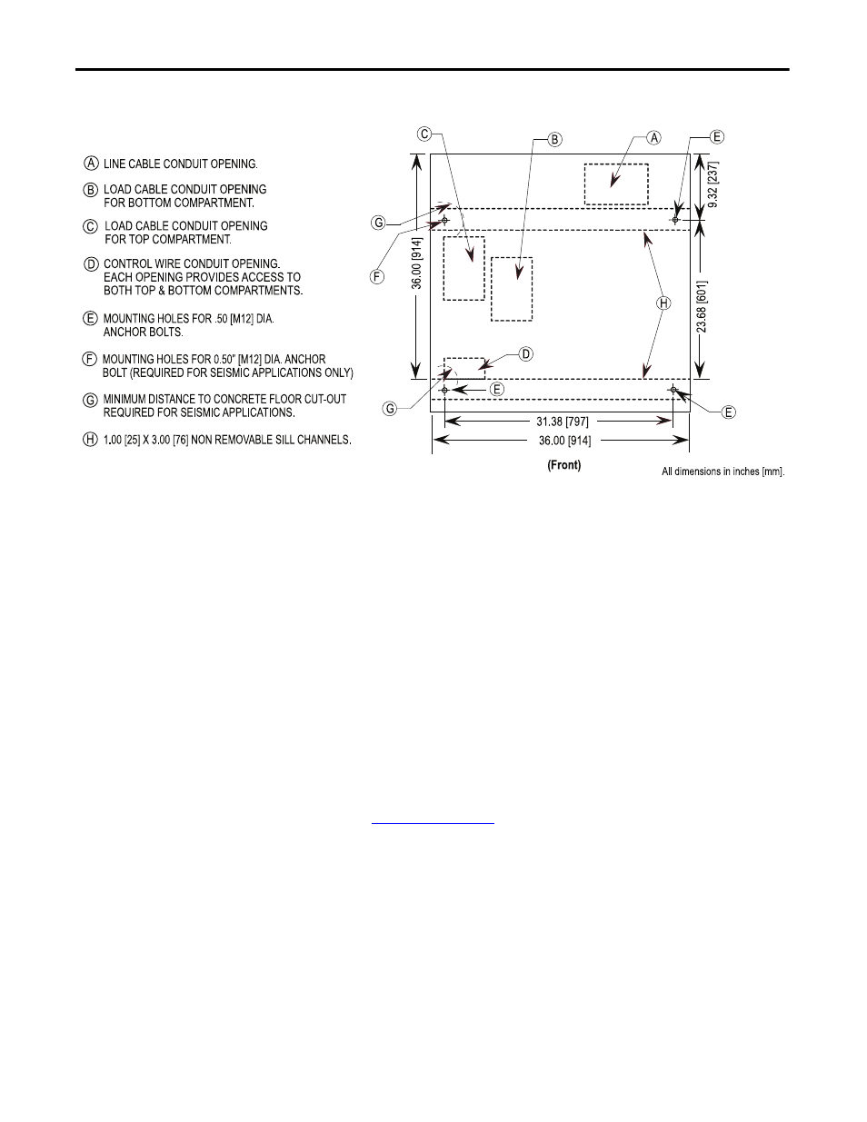
Figure 5 - Cabinet Floor Plan
NOTES FOR SEISMIC APPLICATIONS
• For installations on concrete – the minimum depth and radius of
concrete supporting the cabinet anchors is dependent on seismic loads.
Refer to important information above.
• For installations on a metal structure – the metal plate depth and cabinet
anchoring method is dependent on seismic loads.
Joining Sections
1. Position the left side of the section on a level surface and secure the section
in place with 12 mm (1/2 in. [M12]) floor mounting bolts (refer
to
2. When joining NEMA Type 12, apply a continuous 3 mm (1/8 in.) wide
bead of silicon sealer around the perimeter of one section.
3. Remove the side bus access covers if applicable.
4. Position the right section against the left section. Ensure that the surface is
level.
TIP
Joining hardware can be found in a package mounted on the front of the
shipping skid. Refer to publication MV-QS050_-EN-P for level floor surface
requirements.