Insulated power bus splicing, Figure 38, Figure 39 – Rockwell Automation 1512B MV Controllers, 200/400A Two-High Cabinet, Standard and Arc-Resistant Enclosure User Manual
Page 44
36
Rockwell Automation Publication 1500-UM055G-EN-P - May 2013
Chapter 4
Common Installation
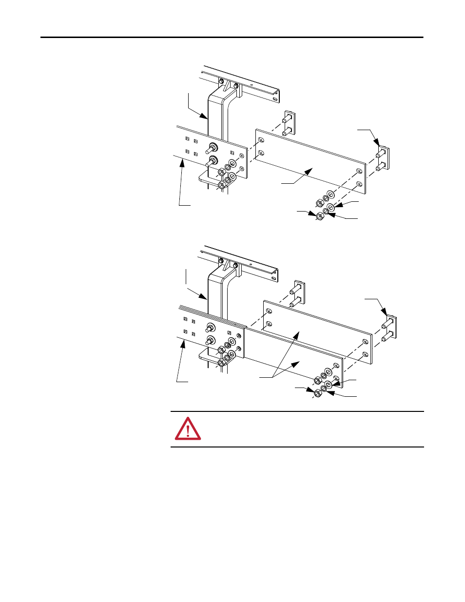
Figure 38 - Typical 1200A Power Bus Splicing Configuration (Viewed from front of cabinet)
Figure 39 - Typical 2000A Power Bus Splicing Configuration (Viewed from front of cabinet)
Insulated Power Bus Splicing
If the starter is equipped with insulated power bus, then a splice kit with insulated
links, insulating boots and tape will be provided. Refer to the kit for installation
instructions.
Bus Clamp
Flat Washer
Lock Washer
Hex Nut
Power Bus
Splice Bar
Bus Support
Main Horizontal
Power Bus
Bus Clamp
Flat Washer
Lock Washer
Hex Nut
Power Bus
Splice Bars
Bus Support
Main Horizontal
Power Bus
ATTENTION: Ensure all barriers are replaced before re-energizing the
equipment. Failure to do so may result in electrical faults and cause damage to
equipment or severe injury to personnel.