Front access – bottom exiting load cables, Figure 33 – Rockwell Automation 1512B MV Controllers, 200/400A Two-High Cabinet, Standard and Arc-Resistant Enclosure User Manual
Page 39
Rockwell Automation Publication 1500-UM055G-EN-P - May 2013
31
Installation – Arc-Resistant Enclosure (ArcShield)
Chapter 3
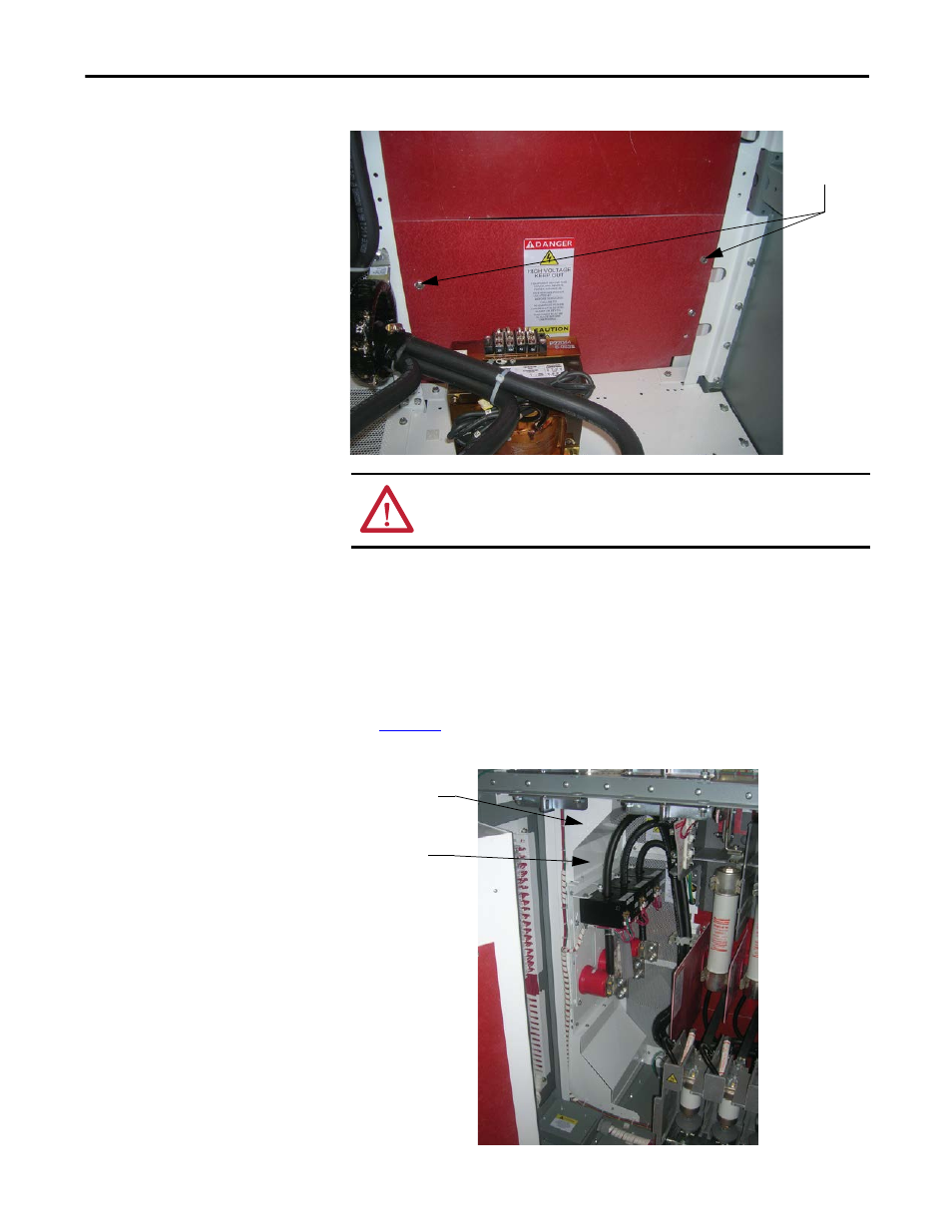
Figure 33 - Access to Right Side of Power Bus
Front Access – Bottom Exiting Load Cables
If the cables in your cabinet exit from the bottom, the procedure to access the
power bus is almost identical to the one above. Follow the procedure for Front
Access - Top Exiting Load Cables, but remove the cable duct barrier and cable
duct boot from the top of the lower power cell, rather than those at the bottom
(see
Figure 34 - Bottom Cable Exit Configuration
Remove self-
tapping screws
ATTENTION: Ensure all barriers are replaced before re-energizing the
equipment. Failure to do so may result in electrical faults and cause damage to
equipment or serious injury to personnel.
Cable Duct Barrier
Cable Duct Boot