Isolation blade switch adjustment, Figure 58 – Rockwell Automation 1512B MV Controllers, 200/400A Two-High Cabinet, Standard and Arc-Resistant Enclosure User Manual
Page 67
Rockwell Automation Publication 1500-UM055G-EN-P - May 2013
59
Maintenance
Chapter 5
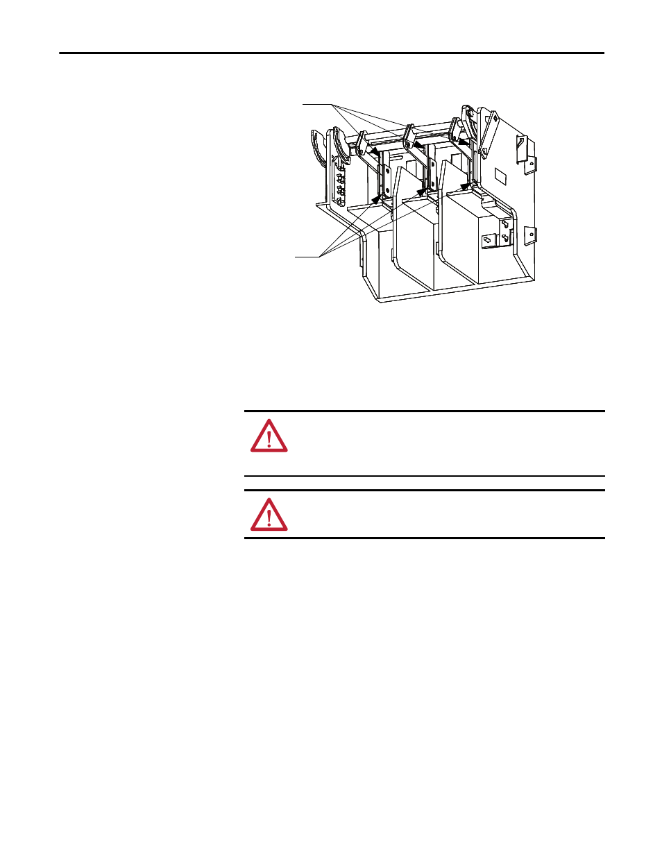
Figure 58 - Isolation Switch Lubrication Points
Isolation Blade Switch
Adjustment
The Bulletin 1500 (Series R) Isolation Switch has been updated to improve
performance. This procedure ensures the isolation switch linkage assembly
operates correctly with the new design change.
1. Insert a screwdriver in the Isolation Switch Defeater, push down and hold
at the bottom position.
2. Actuate the Isolation Switch Operating Handle from Open (black) to
Closed (red) in a continuous movement.
Do not use excessive force or speed in closing the switch. This will cause an
incorrect test result.
Lubricate Isolation
Switch Blades
Lubricate Pivot
Points
ATTENTION: Complete the Power Lockout procedure of the main power bus
before servicing equipment. Verify with a hot stick or appropriate voltage
measuring device that all circuits are voltage free. Failure to do so may result in
severe burns, injury, or death.
WARNING: Use suitable personal protective equipment (PPE) per local codes or
regulations. Failure to do so may result in severe burns, injury, or death.