Ground bus, Incoming line cable connections – Rockwell Automation 1512B MV Controllers, 200/400A Two-High Cabinet, Standard and Arc-Resistant Enclosure User Manual
Page 45
Rockwell Automation Publication 1500-UM055G-EN-P - May 2013
37
Common Installation
Chapter 4
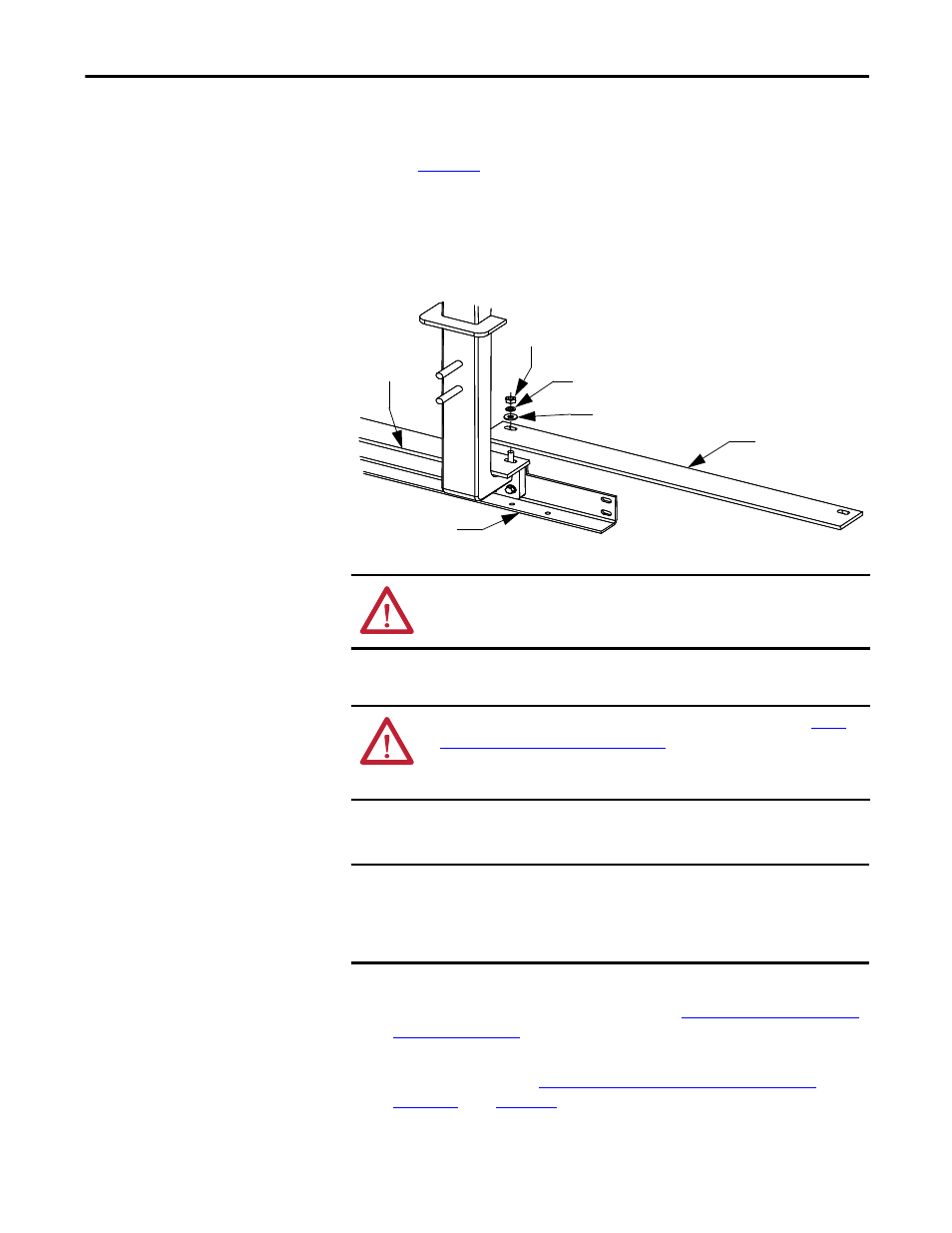
Ground Bus
to determine the correct ground splice configuration and
assemble as shown.
2. Torque the hardware to 15 N•m ± 1 N•m (12 lb•ft ± 1 lb•ft).
3. Check all hardware for correct tightness and replace all covers and plates.
Figure 40 - Typical Ground Bus Splicing Configuration (Front View)
Incoming Line Cable
Connections
Incoming cables are connected to the power bus in the last section on the left.
1. Remove the center-back plate or side plate to access the power bus. If access
to the rear of the unit is not possible, refer to
for either standard or ArcShield enclosures.
2. Connect the incoming power lines to the power bus. Torque to
specifications (refer to
Recommended Torque Values on page 3 of
) (see
).
Ground Bus Support
Main
Ground
Bus
Hex Nut
Lock Washer
Flat Washer
Ground Bus Splice Bar
ATTENTION: Ensure all barriers are replaced before re-energizing the
equipment. Failure to do so may result in electrical faults and cause damage to
equipment or severe injury to personnel.
ATTENTION: To avoid shock hazards, lock out incoming power (refer to
Lock-out Procedure on page 47 of Chapter 5
) before working on the equipment.
Verify with a hot stick or appropriate voltage measuring device that all circuits
are voltage free. Failure to do so may result in severe burns, injury or death.
IMPORTANT
For Non-ArcShield units, cable size should not exceed 1-750 MCM or
2-500 MCM per phase.
For ArcShield units, cable size should not exceed 1-500 MCM or 2-4/0 per
phase. For larger cables, an incoming line module must be used.