Power lock-out procedure, Refer to, Power lock-out – Rockwell Automation 1512B MV Controllers, 200/400A Two-High Cabinet, Standard and Arc-Resistant Enclosure User Manual
Page 55: T (refer to, E (refer to, R (refer to, Power
Rockwell Automation Publication 1500-UM055G-EN-P - May 2013
47
Maintenance
Chapter 5
Power Lock-out Procedure
1. Disconnect and lock out all feeder power supplies to the starter.
2. Move the isolation switch handle to the OFF position.
3. If the unit is equipped with power factor correction capacitors, stored
energy must be dissipated before entering the power cell. Wait at least five
minutes before entering the power cell or dissipate the power using the
following procedure:
a. Verify that the isolation switch handle is in the OFF position.
b. Open the low voltage door.
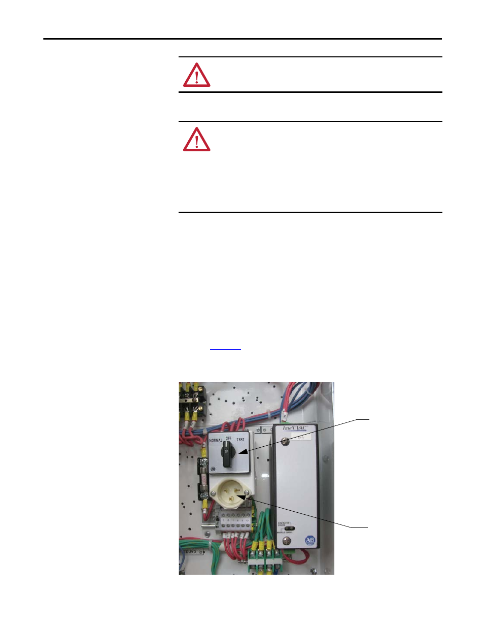
c. Connect the appropriate power supply (120 or 230V) into the auxiliary
control power circuit as shown on the electrical drawing (see
d. Move the control switch to the TEST position.
Figure 46 - Control Panel (IntelliVAC Control)
ATTENTION: Always perform the Power Lock-out procedure before servicing
the equipment. Failure to do so may result in severe burns, injury or death.
ATTENTION: The following procedure requires moving the isolation switch
handle to the ON position. To avoid shock hazards, disconnect and lock out
incoming power before proceeding with servicing the equipment.
Failure to lock out incoming power will result in a live power cell once the isolation
switch handle is in the ON position and may cause severe burns, injury or death.
Rockwell Automation does not assume any responsibility for injuries to personnel
who have not completed the following safety procedure prior to servicing the
equipment.
Control Switch
Auxiliary Power
Receptacle