Figure 57 – Rockwell Automation 1512B MV Controllers, 200/400A Two-High Cabinet, Standard and Arc-Resistant Enclosure User Manual
Page 66
58
Rockwell Automation Publication 1500-UM055G-EN-P - May 2013
Chapter 5
Maintenance
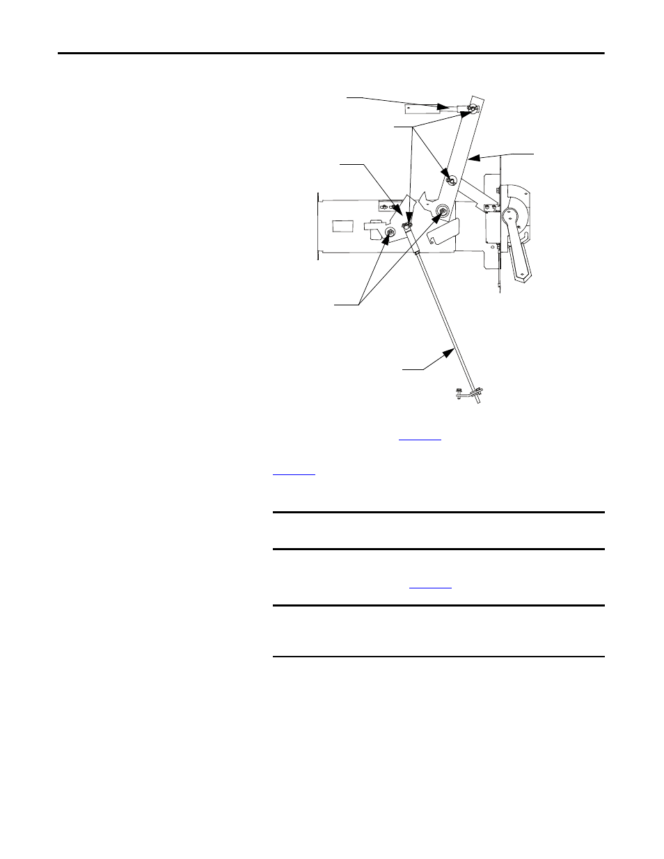
Figure 57 - Isolation Switch Handle Mechanism Lubrication Points
5. Inspect the mounting hardware on the isolation switch operating lever and
). Tighten any loose hardware.
6. Inspect the isolation switch blades and the incoming line stabs (see
). The mating surfaces must be clean and well lubricated.
7. Remove any dirt and dried grease.
8. Lubricate the isolation switch blades and the isolation switch blade pivot
).
Contactor Interlock Rod
Lubrication Points
(at replacement only)
Interlock Lever
Clevis Pins and Cotter Pins
Threaded Connecting Rod
Isolation Switch
Operating Lever
IMPORTANT
Do not scrape or file the parts. This may remove the plating and expose
the underlying copper to corrosion.
IMPORTANT
Lubricate the isolation switch blades a minimum of once per year to
avoid excessive wear to the components and to prevent the isolation
switch blades from overheating.