Isolation switch auxiliary contacts, Adjusting the normally open (isa) contacts – Rockwell Automation 1512B MV Controllers, 200/400A Two-High Cabinet, Standard and Arc-Resistant Enclosure User Manual
Page 72
64
Rockwell Automation Publication 1500-UM055G-EN-P - May 2013
Chapter 5
Maintenance
Isolation Switch Auxiliary
Contacts
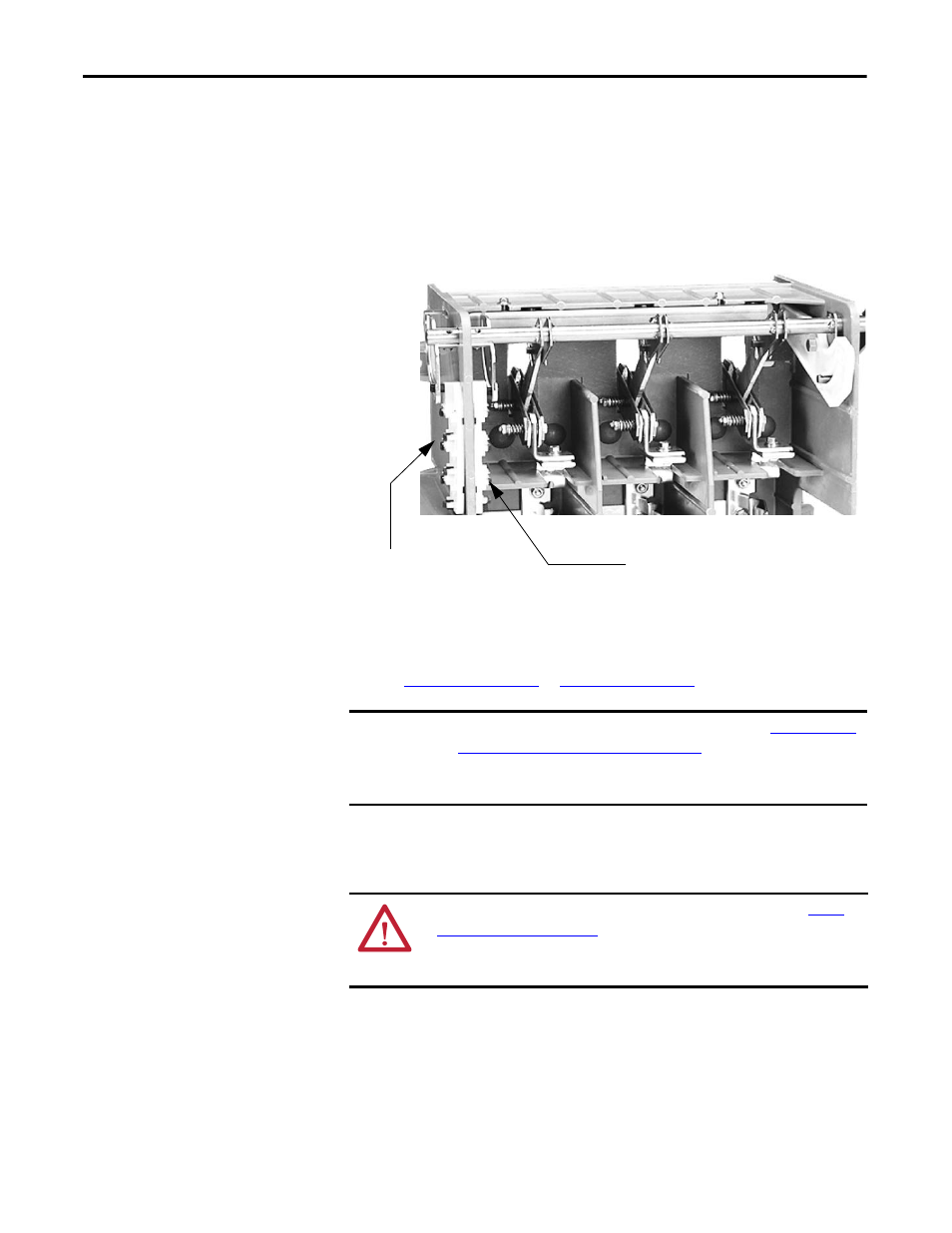
The auxiliary contacts are mounted on the left side of the isolation switch,
slightly below the cams on the isolation switch shaft.
Normally open contacts (Isolation Switch a Contacts - ISa) are on the outside of
the isolation switch housing, and normally closed contacts (Isolation Switch b
Contacts - ISb) are on the inside of the housing.
Figure 65 - Location of ISa and ISb Auxiliary Contacts
ISa and ISb contacts are exactly the same (700 CPM). The cam controls the
normally open or normally closed status of the contacts.
to
for wiring diagrams.
Adjusting the Normally Open (ISa) Contacts
1. Move the isolation switch handle to the OFF (open) position.
2. Loosen the bolt holding the outside cam to the shaft. Do not loosen the
bolt entirely. The cam should not be able to rotate freely on the shaft.
3. Move the isolation switch handle to the ON (closed) position and check
that nothing prevents cam from rotating with the shaft.
ISa Auxiliary
Contacts (N.O.)
ISb Auxiliary Contacts (N.C.)
IMPORTANT
The Isolation Switch Ground Adjustment procedure (refer to
Mechanism Grounding Adjustment on page 62
) must be completed before
adjusting the auxiliary contacts to ensure proper synchronization of the
assembly.
ATTENTION: To avoid shock hazards, lock out incoming power (refer to
) before working on the equipment. Verify with a
hot stick appropriate voltage measuring device that all circuits are voltage free.
Failure to do so may result in severe burns, injury or death.