General plenum layout for arcshield line-up, Plenum bracing – Rockwell Automation 1512B MV Controllers, 200/400A Two-High Cabinet, Standard and Arc-Resistant Enclosure User Manual
Page 86
78
Rockwell Automation Publication 1500-UM055G-EN-P - May 2013
Appendix
B
ArcShield Plenum Installation Instructions
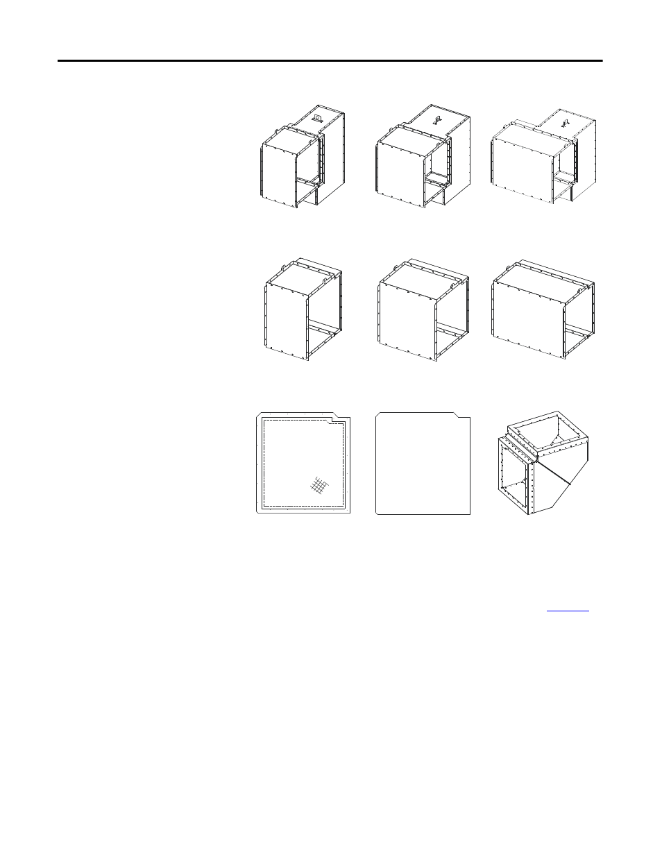
Figure 75 - Description of Plenums and Components
General Plenum Layout for
ArcShield Line-up
An example of a general Plenum assembly configuration is shown in
Plenums of varying widths are mounted directly over the MV enclosures of the
corresponding width. A 0.9 m (36 in.) Exhaust extension assembly is shown
mounted on the extreme right side Plenum of the equipment “Line-up” (can
alternatively exhaust to the left).
18" wide Plenum
Fastened directly over the 0.5 m (18 in.)
wide cabinet
26" wide Plenum
Fastened directly over the 0.7 m (26 in.)
wide cabinet
36" wide Plenum
Fastened directly over the 0.9 m (36 in.)
wide cabinet
18" long Extension
Connected to the last Plenum on the
exhaust end of the “line-up”
26" long Extension
Connected to the last Plenum on the
exhaust end of the “line-up”
36" long Extension
Connected to the last Plenum on the
exhaust end of the “line-up”
Screen Cover Plate
Fastened at the opening of the last
component on the exhaust end
End Cover Plate
Fastened at the opening of the last
Plenum in the “line-up” opposite the
exhaust end to seal Plenum end
90° Elbow Section
Connected at the exhaust end of the
Plenum (or Extension)