Rockwell Automation 1512B MV Controllers, 200/400A Two-High Cabinet, Standard and Arc-Resistant Enclosure User Manual
Page 68
60
Rockwell Automation Publication 1500-UM055G-EN-P - May 2013
Chapter 5
Maintenance
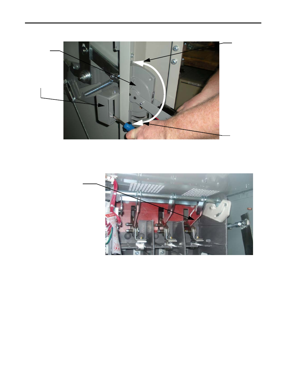
Figure 59 - Isolation Switch Defeater
3. Phase 3 (far right linkage) must be measured for overall travel.
All three phases share the same main actuating shaft but the Phase 3 is the
easiest to measure.
Figure 60 - Isolation Switch Linkage Assembly Location
4. Rest the customer-supplied digital protractor on the bottom of the
isolation switch linkage assembly.
The angle of the linkage must be 180º or slightly higher, with a tolerance
of
0/+6 degrees
.
Closed position
Open position
Isolation Switch
Operating
Handle
Isolation
Switch
Defeater
Isolation Switch Linkage
Assembly (Phase 3)
TIP
If a digital protractor is unavailable, lay a straight edge against the
bottom of the steel lever on the operating shaft to check for parallel
alignment of the red link.