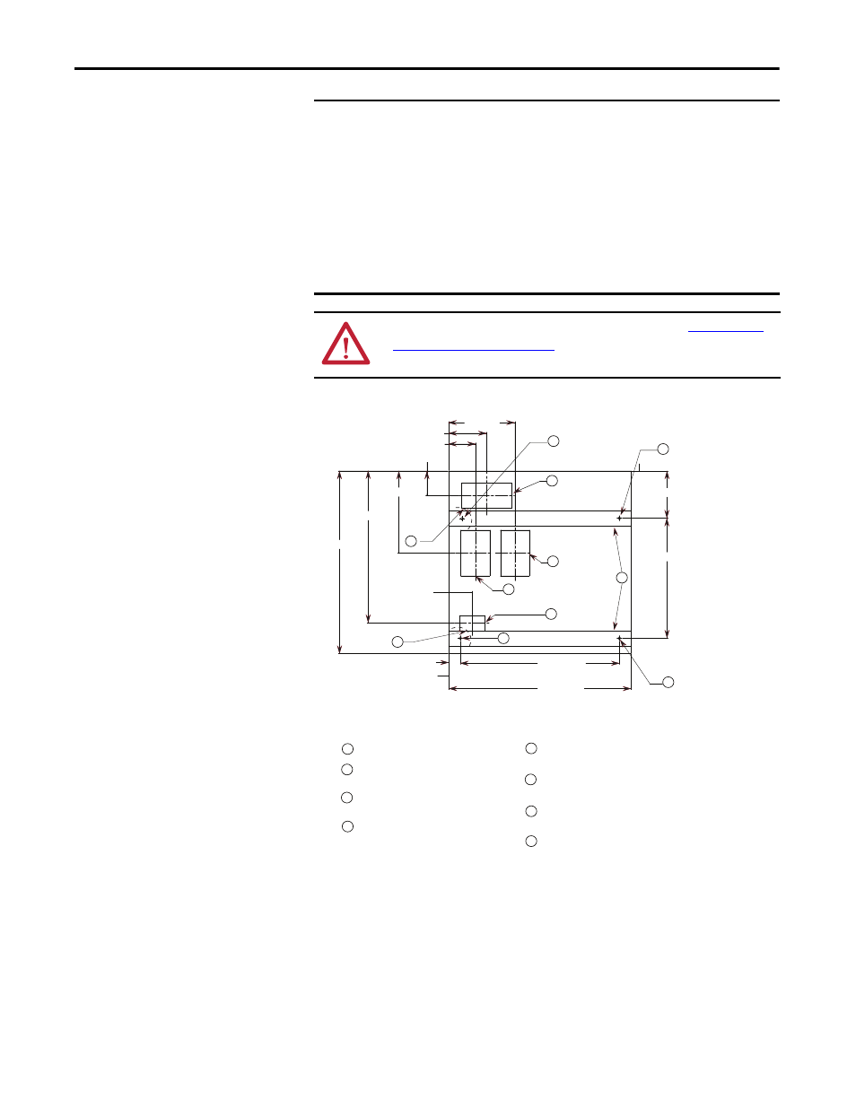
Figure 23, Figure 23 - cabinet floor plan – Rockwell Automation 1512B MV Controllers, 200/400A Two-High Cabinet, Standard and Arc-Resistant Enclosure User Manual
Page 32
24
Rockwell Automation Publication 1500-UM055G-EN-P - May 2013
Chapter 3
Installation – Arc-Resistant Enclosure (ArcShield)
Figure 23 - Cabinet Floor Plan
NOTES FOR SEISMIC APPLICATIONS
• For installations on concrete – the minimum depth and radius of
concrete supporting the cabinet anchors is dependent on seismic loads.
Refer to important information above.
• For installations on a metal structure – the metal plate depth and cabinet
anchoring method is dependent on seismic loads.
IMPORTANT
Pre-determined cabinets have been designed for Uniform Building Code (UBC)
seismic zone 1, 2A, 2B, 3 and 4, and IBC (International Building Code) seismic
activity without overturning or lateral movement, provided they are securely
mounted according to UBC, IBC and local building codes. This can include
concrete pad design, steel floor design and the sizing of cabinet anchors.
Concrete floor cutouts must not be adjacent to floor anchor bolts and must be
sized to seismic load. Consult factory if floor mounting must be reviewed by an
accredited engineer. Many jurisdictions require an engineer from the local area
to review the design. Seismic qualification does not indicate that the
equipment will function properly after a seismic event.
ATTENTION: Complete the Power Lock-out procedure (refer to
Procedure on page 47 of Chapter 5
) before beginning any service procedures to
the unit. Failure to do so may result in severe burns, injury or death.
5.25 [133]
31.38 [797]
36.00 [914]
36.00 [914]
16.17 [411]
30.00 [762]
2.31 [59]
4.62 [117]
9.32 [237]
23.68 [601]
7.50 [191]
4.88 [124]
13.05 [331]
FOR TOP COMPARTMENT.
LOAD CABLE CONDUIT OPENING
MOUNTING HOLES FOR .50 [M12] DIA.
ANCHOR BOLTS.
F
D
C
LINE CABLE CONDUIT OPENING.
LOAD CABLE CONDUIT OPENING
FOR BOTTOM COMPARTMENT.
B
A
5.68 X 9.00
[144 X 229]
3.00 X 5.00
[76 X 127]
D
B
H
E
CONTROL WIRE CONDUIT OPENING.
BOTH TOP & BOTTOM COMPARTMENTS.
EACH OPENING PROVIDES ACCESS TO
BOLT (REQUIRED FOR SEISMIC APPLICATIONS ONLY)
MOUNTING HOLES FOR 0.50” [M12] DIA. ANCHOR
[144 X 229]
5.68 X 9.00
C
5.68 X 9.00
[144 X 229]
A
E
(Front)
G
REQUIRED FOR SEISMIC APPLICATIONS.
MINIMUM DISTANCE TO CONCRETE FLOOR CUT-OUT
H 1.00 [25] X 3.00 [76] NON REMOVABLE SILL CHANNELS.
F
E
E
G
G