Installing the wim in a him bezel (20-him-b1), Figure 2.1 – Rockwell Automation 7000 DPI Wireless Interface Module User Manual
Page 18
2-2
Installing the WIM
•
Using Pocket DriveExplorer for Pocket PC on page 3-2
•
Using DriveExplorer/DriveExplorer Lite on page 3-10
•
Using DriveExecutive on page 3-16
.
When communication is achieved, the WIM status LED will turn
solid blue.
Figure 2.1 Installing the WIM in a Drive
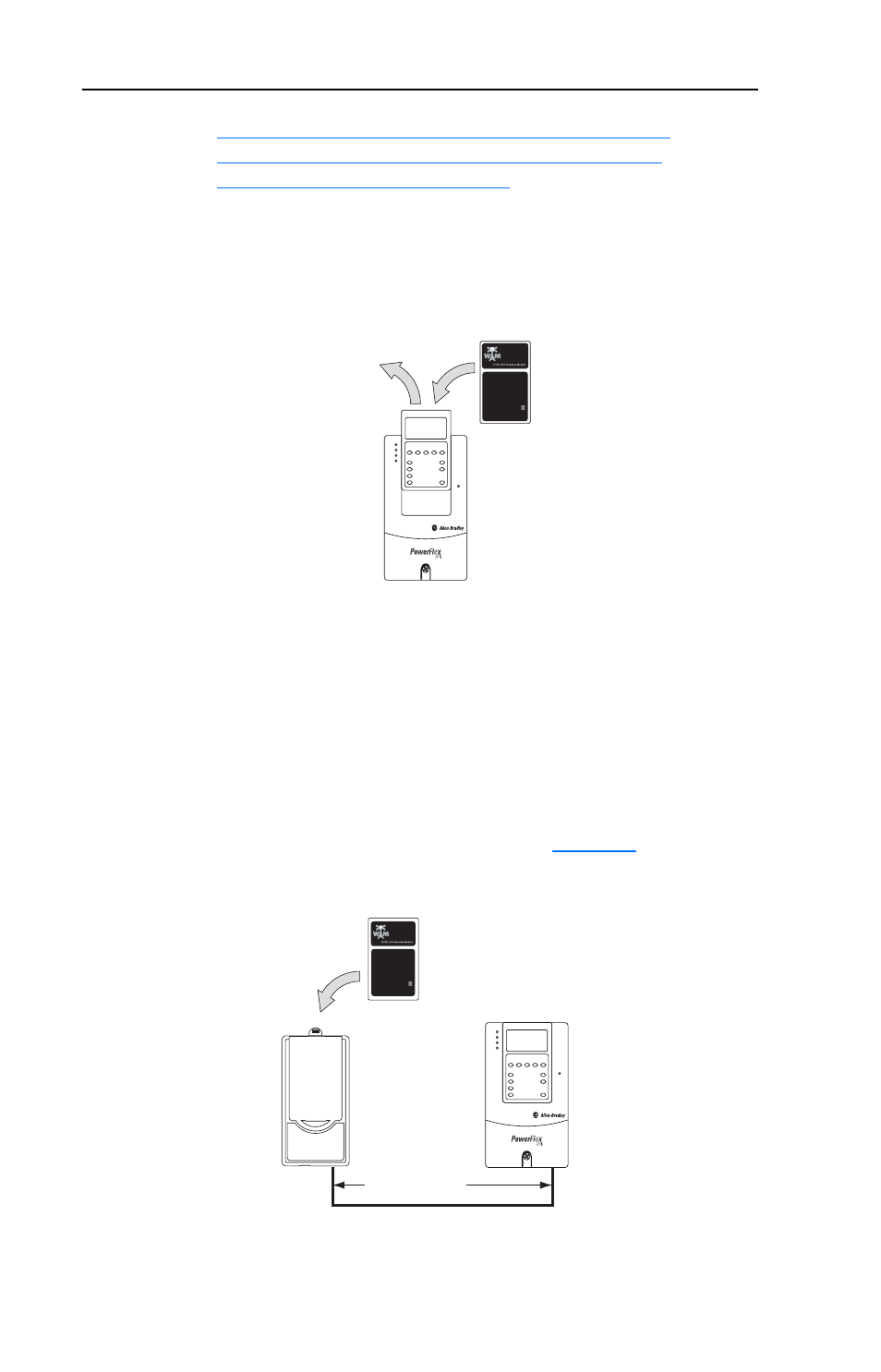
Installing the WIM in a HIM Bezel (20-HIM-B1)
1. If the HIM bezel is not mounted, refer to the HIM Bezel Installation
Instructions (Publication No. 20HIM-IN002…) for mounting details.
2. Route the bezel cable to the drive. Connect the bezel cable to the DPI
port on the bottom of the drive.
3. Install the WIM into the HIM bezel cradle (
).
Figure 2.2 Installing the WIM in a HIM Bezel
20-WIM-N1
(Wireless Interface Module)
HIM
(Human Interface Module)
PowerFlex 70/700 Drive
Contains FCC ID: SNT-2XWIMNX
IC: 5450A-2XWIMNX
This device complies with Part 15 of the FCC rules.
Operation is subject to the following two conditions:
1) this device may not cause harmful interference, and
2) this device must accept any interference received,
including interference that may cause undesired operation
20-WIM-N1
(Wireless Interface Module)
20-HIM-B1
Bezel
PowerFlex 70/700 Drive
with Installed HIM
3 m (9.8 ft.)
Bezel Cable*
*Distance can be increased up to 100 m (328 ft.) using
1202-H* Extension cable(s) or 1202-CBL-KIT-100M cable.
A cable distance greater than 30 m is not CE compliant.
Contains FCC ID: SNT-2XWIMNX
IC: 5450A-2XWIMNX
This device complies with Part 15 of the FCC rules.
Operation is subject to the following two conditions:
1) this device may not cause harmful interference, and
2) this device must accept any interference received,
including interference that may cause undesired operation